Introduction to CNC Tapping
CNC machines are versatile tools used for a variety of tasks, including the lesser-known but essential process of tapping, which is necessary for screwing.
Most CNC machine types like VMC, HMC, Mill-Turns, CNC Lathes, and CNC Routers can use standard Tapping cycles (G84, M03) and Rigid Tapping (G84, M29).
Tapping on a CNC machine presents challenges such as synchronization with the spindle and Z-Axis.
[email_subscription]
Before starting, if you need some more information about taps and tapping check our other articles too;
Table for tap sizes for metric check this link,
Table for tap sizes for Imperial BSPT check this link,
Hand tapping process is explained detailed here,
11 Types of taps for CNC and more explained.
Difference Between Tapping And Rigid Tapping
Understanding rigid tapping and normal tapping, tapping is crucial in the CNC machining process
1) Rigid tapping locks movements in high precision, to turn it on M29 should be used instead of M3.
2) Normal tapping works fine with most machines; however, it is not synchronized and locked like Rigid tapping while moving.
Hint-1) Use rigid tapping with a non-floating holder like standard collet holders.
Hint-2) If you use standard tapping with M03, make sure you use a floating tap holder, so you can compensate small missed movements during tapping. It will prevent breaking taps.
Tapping Using CNC Machines
The power of the spindle motor and the servo motors on the axis motions is crucial for the tapping and rigid tapping process. This is because precise linear synchronization of the Z-axis motor with the tap demands high torque at low RPM. With these properties, we can tap easily without breaking fixtures.
One of the challenges of tapping on a CNC machine is achieving proper spindle synchronization.
Things to consider in CNC machines:
1) A strong spindle motor
2) The manufacturer must know how to control the motor. Because it should make sure that the CNC router motor turns in the right direction and at the right speed.
3) It’s important to choose the right tap and tap holder.
4) The CNC Router needs to work well. Because the tap knife needs to be placed so that it doesn’t go into the holes that the drill made,
Tapping
Depending on which way the screw is going, the tapping cycle can be done either to the right or left.
The cycle of Right Tapping (G84)
[email_subscription]
Cycle G84 is used to make tapped holes. When the bottom of the hole is reached, the tool is retracted by turning the spindle counterclockwise (M04). After the spindle turns, the tool comes back.
During the tapping process, the operator panel’s feed change switch and feed stop button is turned off. So the operator cannot disrupt the synchronized tapping movements by overwriting from the controller.
When the machine is in the tapping cycle, in 1 revolution of the spindle, the z-axis moves 1 pitch(thread step). It should be clear which of the mm/revolution (G94) or mm/revolution (G95) modes to use, and the F (pitch) value should be given correctly
G99 and G98 parameters determine the retract strategy of the cycle. You can think of it as full retract or half retract, you should select it according to your part programming needs. The picture below shows the usage of G99 & G98.
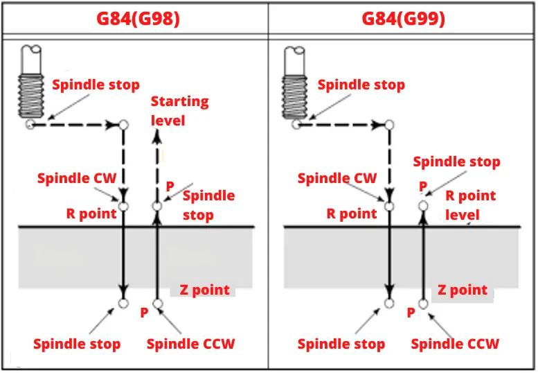
In the G84 cycle, the tool moves in the following ways:
- The spindle turns in a clockwise direction (CW).
- The tool is put where the X and Y axes meet.
- It moves quickly towards the R point (G0-rapid movement).
- The screw is opened from the R point to the Z point ( moves as pitch in synchronization with the spindle).
- The spindle stops turning.
- The tap stays at the bottom of the hole for as long as P (delay parameter) says it should.
- At the end of this time, the spindle turns counterclockwise and goes back to the R point (CCW).
- The spindle stops and waits until P tells it to.
- If the G98 code is used in the cycle, it quickly moves back to the beginning (G0).
This Table Shows Us G84 Tapping Cycle Format In Fanuc System
Siemens Right Tapping Cycle G84
Tapping cycle (CYCLE 84) programming format in Siemens system;
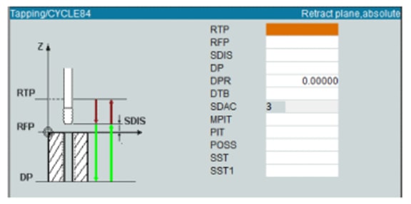
RTP: Rebound distance
RFP: Reference plane
SDIS: Safety distance
DP: Hole depth
DPR: Hole depth relative to the reference plane
DTB: Dwell time at the end of the hole
SDAC: Direction of rotation (3=M3, 4=M4)
MPIT: Standard pitch by screw length (5=M5, 48=M48)
PIT: Screw pitch
POSS: Spindle at desired position stop degree
SST: Number of revolutions
SST1: Rebound speed
Let’s program the part shown in the figure below with G83 and G84 cycles in the Fanuc system; ∅12 mm drill (T06), M14x2 tap (T08)
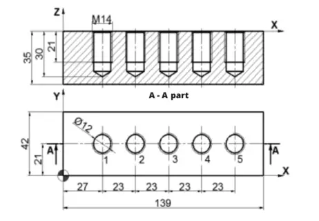
Let’s program the part with CYCLE G83 and CYCLE G84 cycles in Siemens, M14x2 tap (T08)
The cycle of Left Tapping (G74)
Cycle G74 is used to make tapped holes in left thread way.
When the bottom of the hole is reached, the tool is retracted by turning the spindle clockwise (M03). After the spindle turns, the tool comes back. During the tapping process, the operator panel’s feed change switch and feed stop button are turned off.
All the rules that apply to the G84 command also apply to this one. Cycles G84 and G74 are two cycles that are exactly the same. In one, the tool turns in a clockwise direction, and in the other, it turns in a counterclockwise direction.
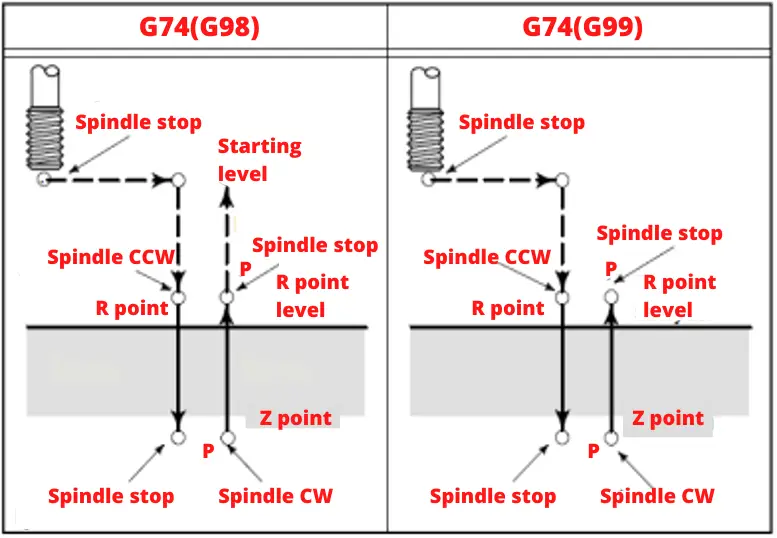
The movement of the tool in the G74 cycle is as follows;
- The spindle is rotated counterclockwise with M4 (CCW).
- The tool comes to the first hole center in the X and Y axis.
- It comes to the R point with rapid movement (G0).
- From the R point to Z point the screw is opened.
- The spindle stops.
- The tap waits at the bottom of the hole for the time indicated by P.
- At the end of this period, the spindle returns to the R point after the spindle rotates clockwise (CW).
- The spindle stops and waits for the time specified by P.
- If the G98 code is used in the cycle, it moves to the starting point with rapid movement (G0).
G74 tapping cycle in the Fanuc system
NOTE: When the tap rotates one revolution around its axis, it advances by the step. Therefore, the F value to be used in the tapping cycle must be equal to the product of the tap rotation speed and the step. Otherwise, the tap will break.
Example Of Left Tapping Cycle
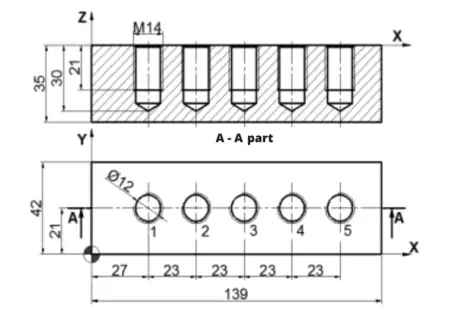
In the tapping process, the feed rate is found by multiplying the number of revolutions given to the machine with the screw pitch (pitch) when the G94 mm/min feed is active.
Feed ( F ) = Pitch x Number of revolutions ( S )
Program Of The Part In The Figure With The G73 And G74 Cycles. ∅12 mm Drill (T06), M14x2 Tap (T08)
Conclusion
Tapping with CNC machines can be challenging, especially when dealing with spindle synchronization. However, with the right knowledge and tools, these challenges can be overcome. Whether you’re using CNC lathes, routers, or other machines, this guide should help you improve your skills.


