Introduction
There are many tools and methods used to measure surface roughness.
From an engineering point of view, the most important ones are:
- Tools with points that are powered by electricity
- Evaluating the surface by touch and measuring how well it works with tools
- There are several kinds of light interference microscopes
- Making copies on the surface
The 1st and 2nd of these methods show a series of profiles on the surface.
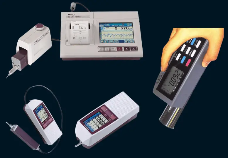
Electrical Pointed Devices
There is a lever on these devices. On the handle is a diamond tip. With this tip, the whole surface of the sample is marked. Electrical signals send information about how the tip moves up and down to the display or printer.
A) Device With E-Core
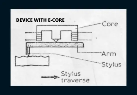
In the picture, the space between the ends of the (E) core changes when the arm at the end of the (Fe) core that is between the two poles of the magnet moves up and down. This change makes the amplitude of electrical signals bigger or smaller. If needed, an interface element boosts the strength of these signals. By making a filtration system, it is possible to print in a straight line.
B) Coil Type Device
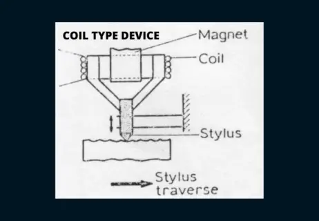
The picture shows a device with a coil. The coil is put on the tip of the diamond. When the magnet is put between the coils, a magnetic field is made in the vertical direction. The ends move up and down with the coil. As the diamond tip moves up and down, the magnetic field changes. This magnetic field has the same strength as the surface’s height and length. Or equal to the number of times the diamond tip moves. In the area where the device works, the frequency may not be sensitive. A (Rc) correction circuit is used to separate out unwanted frequencies.
(Note: The part of the coil that is magnetic makes the coil’s magnetic flux stronger.)
C) Device With A Piezoelectric Crystal
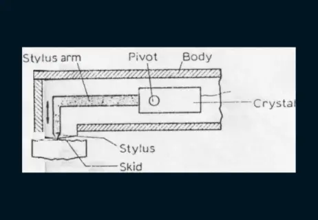
The picture shows a piezoelectric device. When a force is put on a piezoelectric element, it creates tension. The diamond pin is attached to the crystal with a pin. With a pad that slides, the diamond tip touches the surface. When the tip moves up and down, it creates a voltage that is picked up as a signal and sent to the indicator or recorder. The change in voltage is set up to measure how rough the surface is. Little force is used in the pit. The max. peak force is used.
Evaluation Of Surface By Touch And Mechanical Devices
a) Touch evaluation of the surface
The idea behind this method is to compare. Nail control can be done along the surface. Test blocks with roughness values in the (N) series are used to compare. The friction properties of the surface are used to judge how it feels. Since judging the rotating surfaces by touch will lead to more differences, electrical devices with sharp diamond tips (Ra) should be used for control.
Mechanical tools have been made that can measure the touch method. They are put on surfaces that have been ground, polished, lapped, filed, or sanded with these tools. (Ra) values are read as N series equivalents.
b) Working principle of devices
When the thin metal fin surface is pushed into the area to be evaluated, it will either slide or bend, depending on two things.
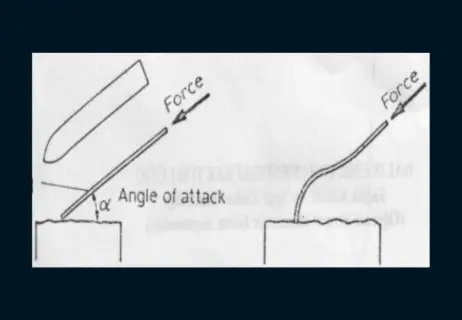
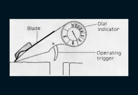
When the angle is less than the critical angle, the fin moves along the surface a little bit. As the angle gets bigger, the fin will start to curve like in the picture. When the surface is very smooth, the critical angle is large. This angle changes depending on how rough the surface is. In the picture, you can see what the device looks like in real life. Through the clear cover, you can see the fin that is attached to the surface. When the critical angle is reached, the N series on the indicator pointer shows the surface roughness values (Ra). The device’s calibration (Ra) is done on hardened test blocks of 0.1 and 0.4 µm.
Dial Depth Device
The rough roughness term (Rz) should be defined for arithmetic mean values above 5.0 m. (Ra). Most measuring tools for electricity are below this value.
The depth device has been made for parts that have been turned, milled, and extruded, among other things. The (Rz) parameter becomes more important than the (Ra) parameter on these surfaces. The device’s benefit is that it can make measurements quickly and doesn’t need graphs.
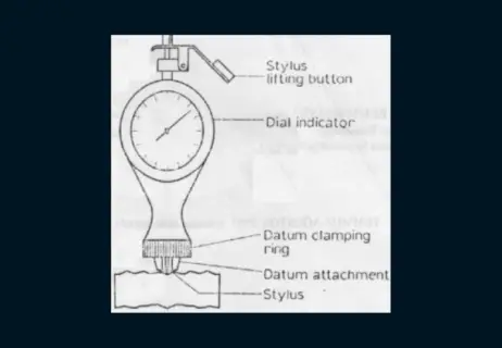
The device consists of an indicator dial with a bar (shaft) inside. Depending on whether the surface is round or flat, the diamond tip can be fixed at two or three points. First, the device is set back to a standard block. Then, by pressing on the area to be measured, the hills could be entered. The tip is then tightened, and a reading is taken. At least 4 times, this process is done again. Its mean is equal to right away (Rz). If you want (Ra), you divide the found (Rz) value by (4). Rz = 4Ra is the roughness value. About 15% of people are tolerant. We shouldn’t forget that we shouldn’t put too much faith in these facts. Rz can be multiplied by 7 (Ra).
Surface Roughness Measurement With Light Interference Microscopes
By making the right changes to the optical system, the shadow-making method can also be used to measure surface roughness on both flat and curved surfaces. Interference shadow bands can only be seen on the surface area that has been studied. So that the shadow is always visible from every angle, you need a camera and very expensive and pricey converters that make the image bigger.
These are devices that are very stable. With these tools, it’s easy to see scratch gaps that are only 0.5 µm wide. In electrical spike devices, stability drops below (2.5) µm.
The gauge is the first place where light interference shadows show up. After that, the shadows of the surface that was measured are compared. This method is used to control how rough the surface of a spherical roller bearing is.
Advantages of this method;
- Even if the surface of the part being looked at is mixed up, a clear image can still be made.
- The method doesn’t hurt the surface because it doesn’t touch it.
- The device doesn’t need to be calibrated over and over.
Assessment Of The Surface With A Surface Copy
This method is used to measure the roughness of a surface when the part is too big to fit in the device. This method is based on pressing a piece of softening plastic onto the surface and then pouring the liquid plastic by building a wall around the sample or passing a ring. The plastic that got dropped is then taken away. With softened plastic, the accuracy is 80%, and with liquid plastic, the accuracy is 100%.