When it comes to CNC machining, achieving the desired surface finish is of the most importance for optimal performance and functionality of mechanical components. This comprehensive guide amalgamates the strengths of two articles to provide an extensive overview of surface finish in CNC machining. From definitions and measurement techniques to factors affecting surface finish, practical tips, conversion charts, and industry standards, this article covers it all. Whether you’re a designer, machinist, or engineer, this article will equip you with the knowledge to achieve superior surface finishes in CNC machining processes.
Definition and Importance of Surface Finish
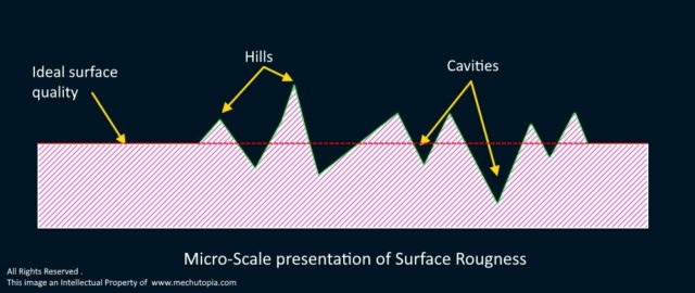
The surface finish is more than just a smooth touch or shiny look. It encompasses the texture of a surface, its roughness, waviness, and lay. These factors are not just for show; they play a pivotal role in determining the quality and functionality of machined parts. The structure of a surface is a landscape of microscopic waves, hills, and valleys on the part’s surface.
While we inspect the surface quality we follow a concept, and this concept gives us the structure of the surface. This structural concept determines the measurement of microscopic waves, hills, and valleys on the surface of the part.
The average height of roughness is one of the most important standard values of the structure of a surface. But making sure the surface isn’t too rough isn’t enough. Before you can measure the properties of a surface, you need to know what causes the imperfection microstructures on the part surface.
The Surface Topology of A Part
The surface structure is better described by the following terms.
Lay Direction: long lines on the surface.
Crater: Small holes on the surface
Waviness spacing: Meaningful group of lines on the surface.
Crack: Crack on the surface which occurs until under the surface.
These features can be measured with a variety of technologies.
This diagram shows how Waviness, Lay, and Roughness are related to each other:
Surface Roughness Parameters and Standards
Several factors influence surface finish in CNC machining. A comprehensive understanding of these factors enables machinists to optimize surface finish and minimize defects.
Factors affecting surface finish
- Tool wear and tool deflection
- Vibration and chatter during machining
- Applying incorrect cutting parameters like wrong feed rates and spindle speeds.
- Inadequate coolant and lubrication
- Poor workpiece clamping or fixturing
- Material characteristics
- Machine linear guide looseness
Surface roughness
It is a part of the texture of the surface and is often shortened to “roughness.” It is measured by how much its normal vector deviates from the shape of a perfect surface. If these differences are big, the surface is rough, but if they are small, it is smooth.
Lines on the surface have short, uneven wavelengths, and when a tool moves from one end of the surface to the other, it leaves many scratches. When measuring surface scratches in the normal direction and in the cross direction, the wavelengths are different (angled dashed line).
Waviness
It is a way to measure the part of the surface texture that is farther apart. It is a broader view of roughness because, more specifically, it can be defined as “irregularities whose intervals are greater than the roughness sampling length.”
The surface is overloaded if the roughness is spread out over different lengths. This kind of shape is called a “ripple.” Changes can happen during surface grinding if parts of the grinding wheel are missing if the joint sump of the machining tool vibrates, or if heat treatments are done.
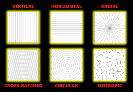
Lay
It is the direction of the surface pattern that is normally determined by the manufacturing method used.
Surface roughness parameters such as Ra (average roughness), Rz (maximum roughness depth), and Rmax (highest peak height) are key indicators for evaluating and specifying surface finish.
Understanding these parameters and their significance is essential for achieving the desired surface quality.
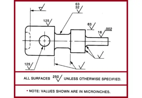
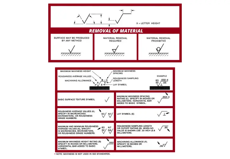
ISO and ANSI standards provide guidelines and symbols for surface finish specifications, ensuring clear communication between designers and manufacturers.
A Detailed Explanation of Surface Finish Units From RA to RZ.
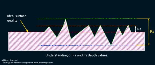
Ra – Average roughness
The surface roughness parameter Ra represents the arithmetic mean of deviations from the centerline of the material. It is the most prevalent method for evaluating the smoothness of a surface.
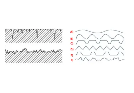
However, despite understanding the average surface roughness through Ra, it is not possible to discern the differences between peaks and valleys. Distinct profiles with varying characteristics may yield identical Ra values.
As a result, the Ra measurement might not provide an accurate representation of the material’s profile. When assessing peak and valley profiles, they can both exhibit the same Ra value. Nevertheless, identical Ra values don’t necessarily indicate that the surface properties of these two profiles are alike.
Here are 6 surfaces that all have the same Ra but are very different in shape.
Rmax – Highest peak height
The Maximum Roughness Value, Rmax, is the largest of values sequentially measured over the evaluation length.
Rz – Ten-point height
The Rz(ISO) parameter, or the Ten Point Height of Irregularities, represents the average height of the five highest-profile peaks and the actual depth of the five deepest valleys within the evaluation length.
This measurement provides a more detailed understanding of a surface’s texture, as it considers both the peaks and valleys, giving a clearer representation of the surface’s irregularities.
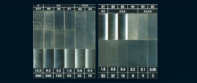
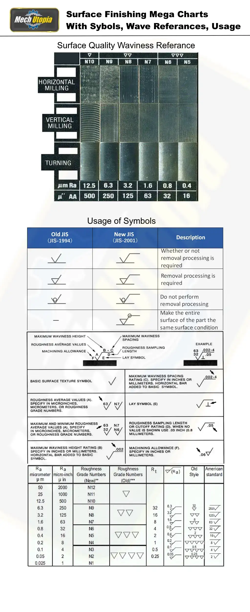
Surface roughness level grades: Standard “N” notations.
Surface roughness classifications employ the conventional “N” notation, allocating a Roughness Grade Number to distinguish various surface textures.
To interchange between Roughness Grade Numbers and Ra Numbers, refer to the table below. Remember that surface roughness values in micro inches are 40 times their corresponding micrometer values.
| Roughness Grade Number (N) | Roughness Average (Ra) in Micrometers | Roughness Average (Ra) in Micro Inches |
|---|---|---|
| N1 | 0.025 | 1.0 |
| N2 | 0.05 | 2.0 |
| N3 | 0.1 | 4.0 |
| N4 | 0.2 | 8.0 |
| N5 | 0.4 | 16.0 |
| N6 | 0.8 | 32.0 |
| N7 | 1.6 | 64.0 |
| N8 | 3.2 | 128.0 |
| N9 | 6.3 | 250.0 |
| N10 | 12.5 | 500.0 |
| N11 | 25.0 | 1000.0 |
| N12 | 50.0 | 2000.0 |
Best Practices For Achieving Superior Surface Finish
To achieve superior surface finishes, adhering to best practices is essential. Optimal tool selection, lead angles, insert geometries, feed rates, and cutting parameters significantly contribute to the quality of the machined surface.
Striking the right balance between the desired finish and cost-effectiveness is crucial for successful surface finish optimization.
Conversion Charts And Practical Tips For Surface Finish
Conversion charts for surface roughness units, abrasive grits, and roughness grade numbers facilitate easy comparison and understanding of surface finish values.
Additionally, practical tips such as adjusting feeds and speeds, using appropriate tooling, considering cutting parameters, and employing advanced machining techniques contribute to achieving optimal surface finishes.
How rough abrasive grits and sandpaper are on the surface
You can use an abrasive or sand the surface to finish it. This chart shows how to go from abrasive grain to Ra values for surface finish.
Metric and imperial surface roughness conversion chart
Surface Finishing Mega Chart
Conclusion
Surface finish plays a pivotal role in the CNC machining process, directly impacting the functionality and performance of mechanical components.
By comprehending the definitions, measurement techniques, surface finish parameters, best practices, and industry standards discussed in this comprehensive guide, designers and machinists can consistently produce high-quality surfaces that meet the intended requirements.
Superior surface finishes enhance product quality, reduce friction, and improve the overall efficiency and lifespan of machined parts, leading to enhanced customer satisfaction and success in the CNC machining industry.