Introduction
In the dynamic world of CNC machining, the ability to simulate programs is a game-changer. Modern CNC machines come provided with applications that allow for G & M code simulations, enabling us to create and control programs in a simulated environment. This powerful feature not only enhances productivity but also ensures accuracy and safety in CNC operations.
The significance of inbuilt CNC simulation
Inbuilt CNC simulation is a crucial feature that ensures the accuracy and validity of G & M codes for a specific CNC controller before the actual machining process begins. This controller-embedded simulation can identify and flag errors before real cutting operations commence, preventing costly mistakes and enhancing operational efficiency.
The Mechanics of CNC Simulation
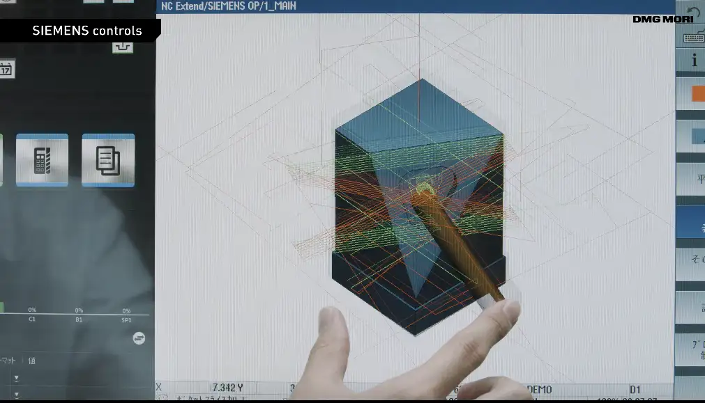
Let’s delve into the simulation capabilities of popular CNC controllers like Fanuc, Mazatrol, and Siemens. These controllers, along with others, offer similar features, making them widely used in the industry.
When the MACHINE LOCK switch is set to ON before the simulation begins, the given machining movements are shown on the machine position indicator, but the machine axes do not move (because of the lock).
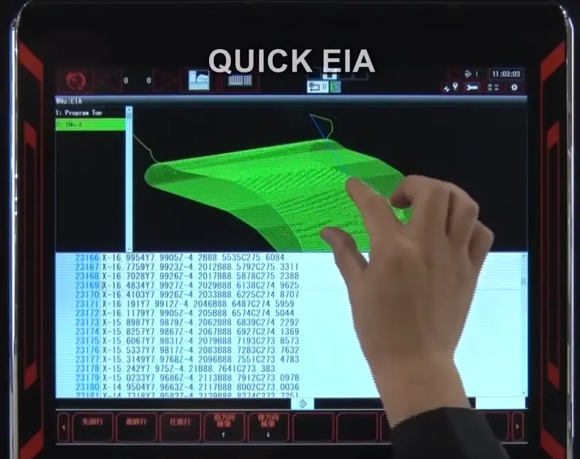
You can make CNC programs in a conversational in-built programming system. Most of the time, graphics and menu-based functions are used to make a program with a conversational programming system.
When the programming is done, most dialogue controls have a toolpath graphic display that shows what will happen during the machining operation.
Practical Examples of CNC Controller Simulation
To illustrate the power of controller simulation, let’s consider a practical example. Suppose we’re using the G83 cycle to drill holes in a workpiece. After writing the CNC part program, we can use the simulation to watch the part being machined by CNC, identify any mistakes, and make necessary corrections.
For example; use the G83 cycle to drill the holes in the piece shown in the picture below. First, use a ∅12 mm drill and then an ∅18 mm drill to peck. Use the G86 cycle to make the top part of the hole bigger.
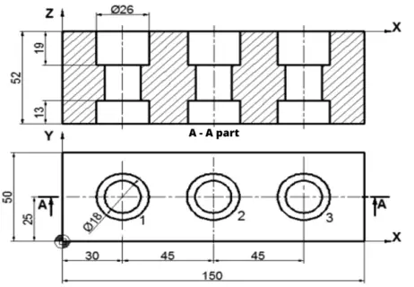
Using the latest G87 cycle, machine the bottom of the hole to make it bigger without taking the part off. After writing the CNC part program, you can use the simulation to watch the part being made.
If there are mistakes, fix them. Check that the workpiece and tools are connected correctly. Process the piece with as much attention to safety as possible.
Tools And Equipment For CNC Simulation
- ∅12 mm drill (T01);
- Spot Drill (T02)
- 18mm drill (T03);
- Boring head (T07);
- Workpiece material C1040;
- Cutting tool material: hard metal insert.
- Any brand CNC controller with solid verifying capability.
Example Program
I will write a small program here for a Vertical machining center to put a mark on the part`s top surface with a spot drill;
O001 (Sample Program number 1)
G00 G90 G40 (Select Absolute system with the rapid move and canceled compensation)
T02 M6 (Change tool)
S1500 M3 (Turn spindle)
G43 H2 Z100. (Set height offset)
G81 X30. Y25. Z-3 R2. F150.
X75.
X120.
G80 (Cancel g83 drilling cycle)
M5 (Stop spindle)
G91 G28 Z0. (Z HOME RETURN)
M30
As a said this program just puts spot drill marks. You can add other features with similar programs.
How to Use CNC Cutting Simulation?
All modern CNC controllers simulate and verify cutting in a similar manner. Here are some common steps you can follow to simulate the cutting process in any CNC controller.
Step-1: First go to the simulation mode or settings page on your controller.
Step-2: In here you should set the blank(stock) size, so your parts verification boundaries can be defined here.
Step-3: Give your part`s blank material coordinates to the controller, so the machine can verify that limit switches do not get hit during the run.
Step-4: You should be able to select verification speed.
Conclusion
In conclusion, the simulation capabilities of CNC machines are invaluable. They ensure our program is safe to work with and prevent costly errors and machine crashes.
Why is it important to use inbuilt CNC simulation?
- Inbuilt CNC simulation guarantees that G&M codes are accurate and valid for a specific CNC controller before actual machining takes place.
- Controller-embedded CNC simulations can catch and flag mistakes before real cutting operations on the machine.
- CAM-based simulations are limited to verifying toolpaths created in the CAM software, on the other hand, embedded verification systems can verify CNC machine-specific operational needs like tool changing, cycles etc.
- In contrast, inbuilt simulation tools provided by the CNC controller can check the G&M codes against the controller’s capabilities and provide alerts to eliminate errors before machining the real part.
- CNC simulation software can improve productivity by reducing setup time, reducing crashes and destroyed parts also reducing the cost of business operations.