Introduction
These days CNC operators and programmer who is familiar with CNC machining cycles are considered a master. Because all machining jobs don’t need to be done by a complex cad/cam system. Basically, we can use in-build machining cycles to fast programs in a CNC controller or with a text editor on a computer.
[email_subscription]
One of the powerful G-Code cycles is the Pocket Milling Cycle. Its powers come from its algorithms which can generate complex circular and rectangular-linear toolpaths with just variables, and G-code properties. G24 and 25 are often used for pocket milling with CNC machines.
What cutter, tool is used for pocket milling?
Endmills are used to machine rectangular and circular pockets.As you can guess pocket milling can be rectangular or circular. Circular Pocket milling can be used as a rough machining operation for bearing beds and housing. Rectangular pocket milling is for machining small pools on the surface of the parts.
Also at the end of this article, we will give some pro tips for you to use these cycles to hack other operations which will show you more professionalism in your workshop.
What is the difference between pocket milling and profile milling?
With profile machining, longitudinal cutting is usually done, while pocket milling involves creating pockets or cavities in a workpiece using various toolpath strategies, such as circular or rectangular patterns, with stepovers dependent on the tool size, shape, and desired finish.The structure of these cycles is like that of face milling cycles. Once the parameters for the cycle have been entered, rectangular or circular pocket milling can be done. For the rectangular pocketing cycle, the code G24 is used, and for the circular pocketing cycle, the code G25 is used.
It is important to set parameters like the size of the pocket, the depth of cut, the point(height) of rapid arrival, and the amount of cutter side-shift (side-cut). Let’s look at them in more depth.
How to do pocket milling?
First decide your stock allowances, than basic pocket milling can be done with this steps;1-Touch to top of workpiece.
2-Plunge with suitable plunging feedrate.
3-Machine countours with side steps until come to edge of pocket.
4-Repeat step-2 and step-3 untill you arrive to final depth.
5-Give a finish pass to the walls in full-depth.
6-Give a finish on floor surface of pocket on final depth.
Rectangular pocket milling G24
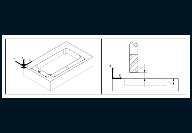
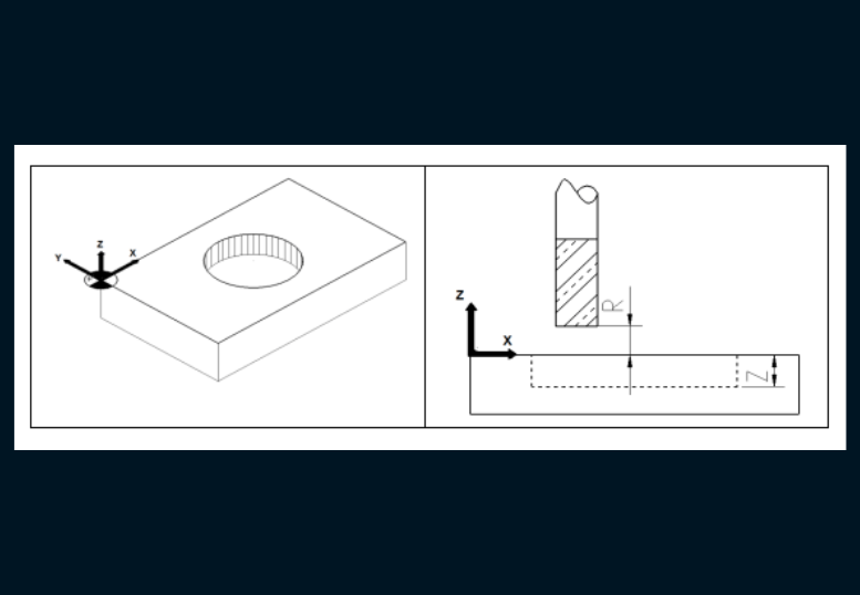
Before continuing, let’s understand how pocket milling works in general. In the below figure as you can see W, and L variables define the width and height of the pocket, R-value is the depth of the cut. As you can guess we shouldn`t plunge all depths of cut at one time to avoid tool breakage.
So we should plunge a 2mm machine pocket and plunge again and machine pocket again. This cycle continues until we hit the final depth. Let us say we machine a pocket that has an 8mm (0.315 inches) depth.
So if we plunge 2mm(0.079 inches) at one time then it will take 4 pocket machining at the depths of -2mm,-4mm,-6mm,-8mm, (in inches -0.079,-0.157,-0.236,-0.315). Also, we should give a finish pass on the final depth, so the maximum plunging depth should be 7.9mm so we can give a 0.1 finish pass.
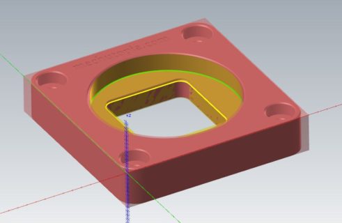
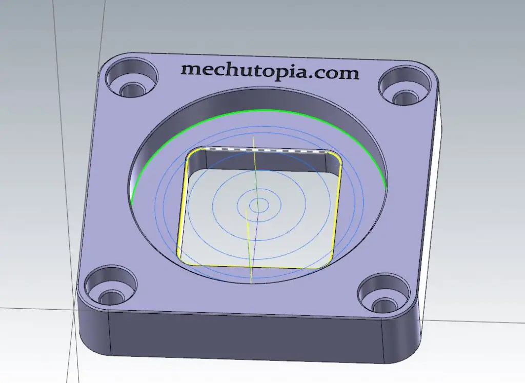
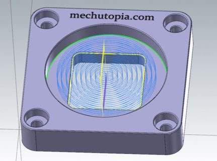
Check the pictures below;
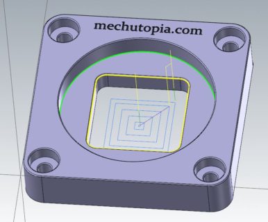
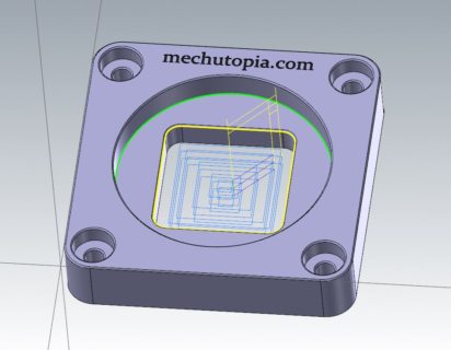
On the right picture, you can see a rough cut, and on the left a final cut for the bottom and walls of the pocket. In our example part the pocket explodes on the bottom so just a contour finish operation can be used too to save time.
G24 rectangular pocket milling cycle writing format in the Fanuc system.
G24 X…Y… L…W… Z… R… Q… D… F…;
X,Y : Coordinates of the lower left corner of the pocket
L : Pocket size on the X-axis (mm)
W : The width of the pocket on the Y-axis (mm)
Z : Pocket depth (mm)
R : Safety distance (mm)
Q : The cutter’s side-shift distance for the next chip (mm)
D : Plunge the amount in the Z axis (mm)
F : Progress (mm/min.)
If you follow this draft you can cut directly from Fanuc MDI mode or the in-memory program. You need to turn your spindle and give preparation G-codes before cutting. Further, you can see prep. G-codes.
This is an embedded pocket cycle for Siemens controllers.
POCKET3 (RTP, RFP, SDIS, DP, DPR, LENG, WID, CRAD, CPA, CPO, STA, FFD, FFP1, CDIR, FAL, VARI, MIDF, FFP2, SSF)
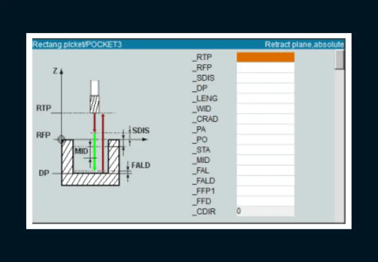
RTP : Rebound distance
RFP : Reference plane
SIDS : safety distance
DP : Pocket depth (absolute)
DPR : Pocket depth relative to the reference plane
LENG : Length (length) of the pocket
WID : Pocket width (width)
CRAD : Corner radius
CPA : X value of pocket center/corner
CPO : Y value of pocket center/corner
STA : Pocket angle (0-180 degrees)
FFD : Plunge feed
FFP1 : Pocket emptying advance value
MID : Immersion depth (amount)
CDIR : Machining direction (2 = clockwise, 3 = counter-clockwise)
FAL : Fine chip allowance for peripheral surfaces
VARI : 0= Machining the pocket to full-size 1=Roughing and leaving fine chips, 2=Finishing the chips
MIDF : Maximum plunge depth (feed) when finishing
FFP2 : Cutting feed for finishing
SSF : Speed for finishing
Rectangular pocket milling cycle (Siemens)
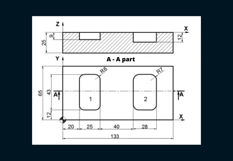
Let’s program the above part with the G24 cycle in the Fanuc system;
∅12 mm Carbide flat-end milling cutter (T09)
∅14 mm Carbide flat tip end mill cutter (T07)
Let’s program the part with the Pocket cycle in the Siemens system;
∅12 mm carbide flat tip end mill cutter (T09)
∅14 mm carbide flat tip end mill cutter (T07)
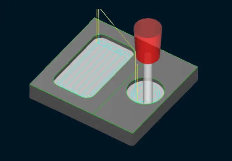
Circular pocket milling G25
A circular pocket milling is done on a part with this cycle and it is just a circular version of the rectangular pocket cycle. Here, the cutter quickly moves to the specified height and the center of the pocket, then slides out from the center to mill the pocket. After each depth passes, it goes back to the middle and keeps going. This process keeps going until the depth of the pocket is reached. The Diameter is a big difference here.
In the figure below you can see the pocket roughing and finishing.
G25 Circular pocket milling cycle writing format.
G25 X… Y… I… J… Z… R… Q… D… F… ;
X,Y : Coordinate a point on the circle
I, J : Circle center coordinates
Z : Pocket depth (mm)
R : Safety distance (mm)
Q : The cutter’s side-shift distance for the next chip (mm)
D : Plunge amount in Z axis (mm)
F : Feed (mm/min.)
POCKET4 (RTP, RFP, SDIS, DP, DPR, PRAD, CPA, CPO, FFD, FFP1, MID, CDIR, FAL, VARI, MIDF, FFP2, SSF)
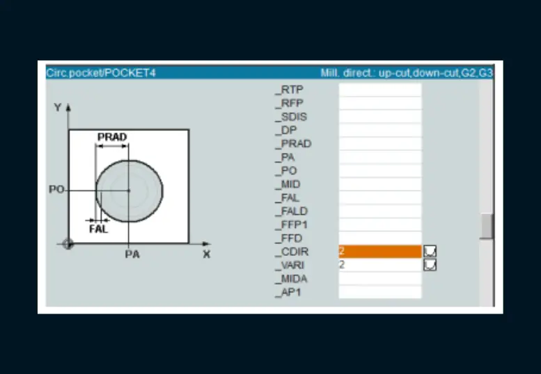
RTP : Rebound distance
RFP : Reference plane
SIDS : safety distance
DP : Pocket depth
DPR : Pocket depth relative to the reference plane
PRAD : Radius of pocket
CPA : Abscess of pocket center/corner (x value) absolutely
CPO : Absolute ordinate of pocket center/corner (y value)
FFD : Plunge feed
FFP1 : Sideshift advance value
MID : Maximum plunge depth
CDIR : Machining direction (2=clockwise, 3=counterclockwise)
FAL : Fine chip allowance for peripheral surfaces
VARI : 0= Machining the pocket to full size 1= Roughing and leaving fine chips, 2= Finishing
MIDF : Maximum plunge depth when finishing
FFP2 : Finishing
SSF : Speed for finishing
Example of circular pocket milling cycle;
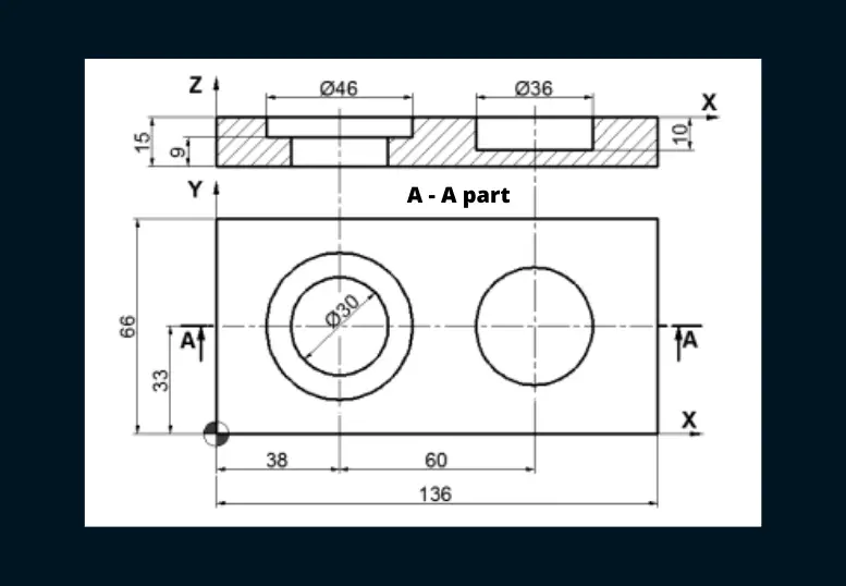
Let’s program the above part with the G25 cycle in the Fanuc system;
∅16 mm carbide-coated flat end milling cutter (T03)
[email_subscription]
Let’s program the part with the G25 cycle in the Fanuc system;
∅16 mm carbide flat-end milling cutter (T03)
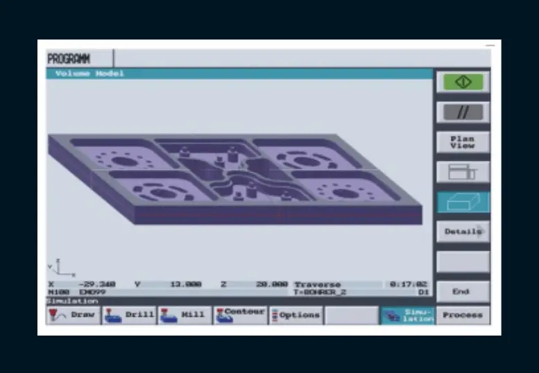
Simulation of cycles and application on the machine
After the program is written, the movements of the cutter are checked on the screen of the simulation, and any errors in the program are looked for. If there are mistakes, they can be eliminated before cutting.
When the machine lock switch is turned ON before the simulation begins, the progress movements shown on the machine position indicator are shown, but the machine axes do not move (Lock).
In the Siemens system, the movements of the cutter are tracked in two dimensions, and at the end of the simulation, a 3D view of the part that was cut is shown.
On the simulation monitoring screen, the part profile and tool paths can be checked by simulating the CNC program written by the editor. If there are mistakes in the program, it can be sent back to the editor to be fixed.