Introduction
- Introduction
- Face Milling Feeds and Speeds Calculator
- What Is Face Milling?
- Stages of the Face Milling Process
- Most Efficient Way Of Using Face Milling Tools?
- Types of Face Milling Tools
- Using a 45-degree Face Mill vs. a 90-degree Face Mill: Pros and Cons
- How to Program Face Milling Operations?
- Face Milling Cutting Feed And Spindle Speeds
- Conclusion
Face Milling Feeds and Speeds Calculator
Results:
Cutting Speed (VC, m/min):
Feed Rate (mm/min):
Spindle Speed (RPM):
In this article, I want to talk about the face milling operation. Facing operation is one of the common operations which you can do on CNC machines. Everywhere, every workshop shop has dedicated face milling heads and these face milling heads enable you to machine flat surfaces easily. Yes, they are specially designed for machining flat surfaces and they can exist in a wide range of diameters between 33mm to 100mm. However, these big boys come with their challenges, to use them properly you need to have enough knowledge to use them. In this article, we will deep dive into usage, face milling feeds and speeds, and tool holding, best practices.
What Is Face Milling?
Milling operation, at its core, is the process of removing material from a workpiece with the help of a rotary cutter. The cutter rotates at a high speed, and as it is fed into the workpiece, it cuts away material to the desired shape. The term ‘milling‘ is derived from the fact that during the process, the workpiece is moved or ‘milled’ around the stationary cutting tool, or vice versa.
Face milling is specialized in machining flat surfaces of mechanical parts. The largest surface area of the part can be machined with face milling. Let’s don’t forget to mention that the face mill is mostly called “facing milling head” in the industry due to its bigger size compared to the other tools.
Stages of the Face Milling Process
The milling process can be broken down into several stages:
- Setup: This involves preparing the milling machine and securing the workpiece in place.
- Tool Selection: The appropriate milling cutter is chosen based on the material of the workpiece and the type of milling operation to be performed.
- Milling: The actual process where the cutter removes material from the workpiece.
- Inspection: The final stage where the milled workpiece is inspected for accuracy and quality.
Each stage plays a crucial role in ensuring the success of the milling operation.
Most Efficient Way Of Using Face Milling Tools?
Face mill cutters (heads) are designed to remove a lot of material in a short time. With these face-milling tools, you can machine flat surfaces, and don’t forget this is mostly designed for rough cutting and to get a nice surface finish you need to increase your final spindle speed and reduce feed rate. you need to improve those variables to catch perfect surface finishes. Less depth passes on the basement can cause cutting tips to wear easily, so they are mostly designed with the working very high depth.
From my experience, I can say that if you don’t plunge enough depth cutting edge resistance on the tip will cause wear tips fastly. Cutting tips on the milling head need to engage the maximum cutting depth it can. In this way, you can use those tips longer.
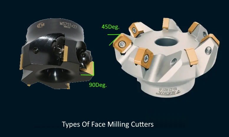
Types of Face Milling Tools
mostly face mills they are very similar to each other. All does just one Mission and this mission is cutting flat surfaces in a high range of material removal rate. A very commonly used one is which is called a right-angle tip face mill cutter and the second one is a 45-degree face milling head.
If we go one by one with the explanation of Face Mill cutters;
1) Face Mill 45º
If we go one by one with the explanation of Face Mill cutters, I can say from my experience that 45-degree face mills this is very good for rough operations. Their design guarantees cutting efficiency because 45 DEG. placed cutting tips reduces cutting stress by %50. In this way, the horizontal Y and X axis share the cutting stress with the Z axis. Because of Z axis carries a spindle and that 45DEG. tips on Face Mill push the Z axis on the Z+ way(which is the most rigid way).
- This kind of Face Mill cutter is more suitable for single-level face-milling operations.
- The surface machined with this tool can require a secondary tool to finish edges and corners. Because 45 DEG. the tip will leave material on the machined surface.
- Weak CNC machines can run this Face Mill.
2) Face Mill 90º
With 90DEG. Face Mill, you can have heavy cuts and harp pocket edges. Because 90 DEG. tips will clear all material from the surface. It does not include a secondary diameter of 45 DEG. Face Mill includes. From my experience, I found out that this kind of Face Mill cutter generates a lot of stress on the CNC machine. So Face Mills with 90DEG. cutting edge is good for heavy-duty machines, and with less depth of cut weak machines can operate this tool too.
- Multi-level surfaces can be machined due to the 90 DEG. cutting tips.
- Rough and Finish operations can be finished with the same Face Mill cutter(90 DEG).
- Heavy-duty machines can achieve very efficient cuts. Weak CNC machines can run with less DOC.
Using a 45-degree Face Mill vs. a 90-degree Face Mill: Pros and Cons
Fly cutters are used for face milling too and we wrote about it on the website check this link.
If you can, use a lead angle cutter when milling, this will help you get more done and avoid problems. The lead angle affects how thick the chip is. The chip-thinning effect is more substantial the steeper the lead angle.
Pros
- Lessens the noise.
- Possible to feed at higher rates.
- Less radial force going into the bearings of the spindle.
- Entry shock is kept to a minimum.
- Less breakage on the corner of the workpiece.
- The axial and radial cutting forces are well balanced.
Cons
- Can make the exit side of the cutter rotation chip or burr.
- No corner milling at 90 degrees.
- A larger body diameter can cause fixture clearance problems.
- Due to the lead angle, the maximum depth of cut was cut down.
How to Program Face Milling Operations?
Face milling operations are easy to program rather than others. Because mostly you don’t need to deal with the boundary because your machine is mostly just the top of the part. So you don’t need to calculate clearance on side edges. Because of this with enough large diameter Face Mill, you can machine the top of the part with a single toll path.
CNC machines can be machines in 2 ways, CAD-CAM systems and Handwritten G codes. So same ways can be applied to Face Milling programming too. Let’s have a look at them.
Using CAD-CAM to generate Face Milling programs
Most CAD-CAM systems have special Face Milling commands to make Face Mill programming easy. Check the picture below which shows the Mastercam`s dedicated face milling command.
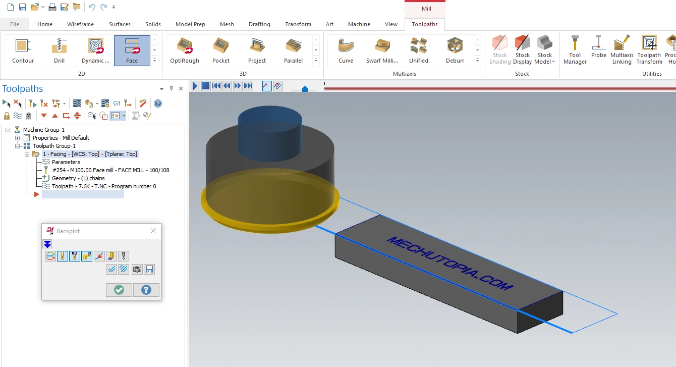
But this toolpath is not optimal, because the whole top surface can be machined by single tool movement due to the narrow part size. So in this situation dealing with inbuilt parameters is too time-consuming. So my solution is generating a single toolpath with another operation. Contour machining can be used as a face milling operation if you close the tool compensation. In the below figure, you can see how I generated a single toolpath Face milling operation with a contour toolpath. If a part was not narrow that much I wouldn’t need it but in this case, my face mill is wider than the part so it can be machined with a toolpath to save time and reduce cost.
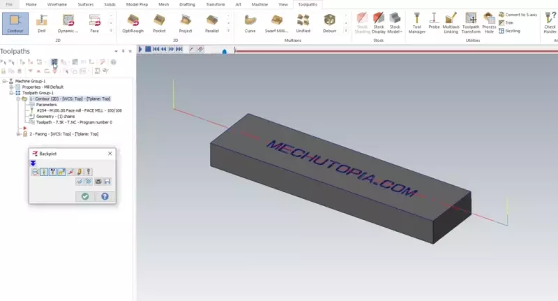
As you can see you can play easily for your specific need.
Using G-Codes for Face Milling Programs
As I mentioned before Face Milling is an easy operation, so it is mean you can program it manually with handwritten G-Codes too. In the below section, you can find a G-Code program for Face Milling.
%
O001
G00G40G80G21
T1M6(Tool Change)
S500M3
G43H1Z100
X0.Y0.
G01Z0.F600. (plunge line)
X250.F500. (feed line)
G00G91G28Z0. (home returning line)
M05
M30
%
Face Milling Cutting Feed And Spindle Speeds
Cutting feeds and spindle speeds for a Face Milling operation depend on a couple of variables. Those variables also are the same for almost all other milling operations. But there are some special bullet points for Face Milling. Let’s have a deeper look at it.
Face Mills generally has larger diameter so as thumps of rule in machining you should use slower cutting speeds for large diameter cutters.
Face Milling operation occurs mostly as roughing operation. To have a stable rough cut you need to reduce spindle speed.
Face Milling heads are capable of cutting high-depth of cuts. Low spindle speeds increase the cutting Torque of the Spindle and allow all cutting teeth to engage properly to material.
As you can feel the most important thing is low spindle speeds are the key to Face Milling. I am going to share my favorite tested feeds and speeds here. Those feeds and speeds are delivered from the manufacturers cutting data.
| Material | Feed per Tooth (mm/tooth) | Speed (RPM) | Feed Rate (mm/min) | Cutting Speed (VC, m/min) |
|---|---|---|---|---|
| Aluminum | 0.11 | 1,500 | 990 | 298.45 |
| Stainless Steel | 0.035 | 400 | 126 | 79.58 |
| Carbon Steel | 0.055 | 1,000 | 330 | 198.94 |
Conclusion
Face Mill cutters are very often used cutting tools for mechanical part manufacturing and CNC machining. It has its tool path generating rules and is mostly easy for others. As look deeper into face milling, it’s important to remember that every decision and technique plays a significant role in achieving the best results.