- Importance of Reading and Writing G-Code
- Understanding G-Code
- Reading G-Code Commands
- Examples of G-Code Commands and Their Functions
- Using G28, G30 Home Returning Commands
- G-Code in CNC Milling and Turning
- G-Code and the Cartesian Coordinate System
- Tool Compensation with G-Code
- Understanding Circular Interpolation G02-G03
- G-Code Program Line numbers
- CAD/CAM Softwares And G-Code Generation
- Manual G-Code Programming
- Conclusion
In CNC machining, we use a programming language called G-code. This programming language, often considered the “mother tongue” of CNC machines, is the primary method of communication between human operators and these highly sophisticated machines. In my experience, I have invested significant time in learning G-code. It is a vital part of modern manufacturing technology. If you use 3d printers and additive machining technologies probably you will never write a manual G-Code program. Because they come with their special CAM and Printing software.
The ease of learning G-code can be subjective and may vary depending on an individual’s background and experience in CNC machining. For someone with a solid foundation in machining and programming, learning G-code might be a more straightforward endeavor. However, for starters, it may require time and effort. Like any language, mastering G-code demands practice, dedication, and a keen understanding of CNC machining principles.
if you want to have a look at common G-Codes and M-Codes I have a comprehensive list of posts for that
Standard G-Codes and M-Codes For CNC Lathe(Turning)
The Ultimate Guide to Standard G-Codes and M-Codes For Milling
CNC G-Codes G00 and G01 With Examples
CNC Lathe – Grooving with G Code Examples
Pocket Milling Cycles (G24, G25) With CNC Milling
To clear up confusion about M-Codes; Miscellaneous Codes are functional codes in CNC programming. You will often hear just G-Code programming, when you hear this be sure these G-Code programs include M-Codes too. It is too long to pronounce so CNC machinists often use G-Code programming terms even if their programs include M-codes too.
Writing a CNC G-Code program without M-codes is impossible because you need to turn on the spindle, open and close the coolant, and change the tool. While G-codes take care of geometrical movements M-codes take care of the functions of machines like turning things on and of.
G-code, in essence, is a series of instructions that guide CNC machines on how to move, what path to follow, and what operations to perform. It’s like a roadmap that directs the machine on how to transform a raw piece of material into a precisely crafted part. From simple operations like drilling holes to complex tasks like creating intricate 3D surfaces, G-code commands make it all possible.
Importance of Reading and Writing G-Code
With G-Codes, you machine simple shapes easily. For example, if you want to machine a key way you can just plunge and feed the tool with G01. Then your G-code would be like this: G01 z-10 F120; G01 X30.F400.;
You may want to drill just a whole again you can just use G01 to move the machine on a straight line.
In my experience, I found myself a lot of time editing raw G-Code programs during the machining process. Because some time you need to change machining parameters like feed rate, and spindle speed, or add another function like opening coolant. This is very often the usual workflow of a CNC operator. So you must know how to read G-Codes and M-Codes so you can alter them to your specific need or add a new line to the program.
G-code commands control every aspect of the machining process. G-code directs machine movement on the X, Y, and Z axes. It controls spindle speed and coolant management. In essence, G-code is the conductor that orchestrates the symphony of operations that take place within a CNC machine.
Moreover, G-code allows for a high degree of precision and repeatability. Once a G-code program is written and tested, it can be used to produce identical parts with pinpoint accuracy, time and time again. Precision is vital in industries like aerospace and medical device manufacturing. Even minor deviations can cause major issues.
Throughout my experience as a CNC machinist. I’ve grown to value the strength of G-code. Mastering this language unlocks a wide range of possibilities in CNC machining and programming.
Understanding G-Code
G-code is widely recognized as the standard programming language for CNC machines. However, there are also proprietary languages and variations that some manufacturers might employ.
While G-code serves as a standardized language for CNC machines, variations exist among different machine manufacturers and models. These variations, often referred to as dialects, might include additional commands or slight differences in syntax. It’s crucial for operators to be familiar with the specific G-code dialect used by their CNC machine to ensure accurate and efficient operations.
G-code, while seemingly complex at first look, becomes a fascinating puzzle to solve once you delve into its line of programs. G-code communicates directly with the CNC machine, guiding its movement, cutting locations, and tool changes. You should recognize a pattern while reading or trying to understand any G-Code program. Because every CNC program has a pattern and I explain it below;
% (Every G code program must start with the % percentage symbol)
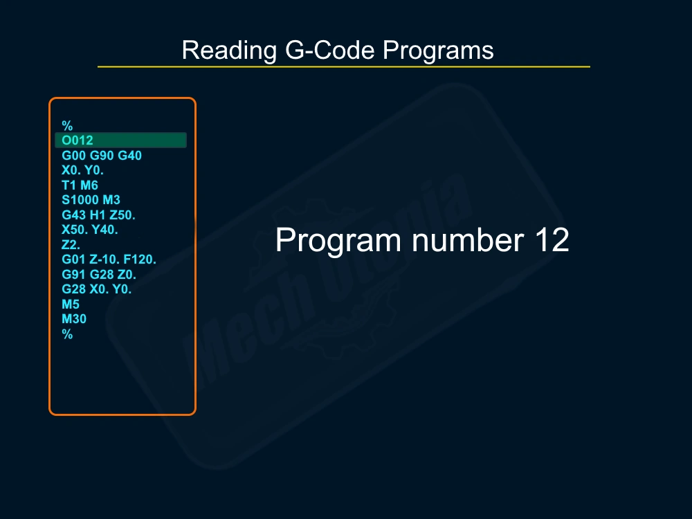
O0012; ( This is the program number it must start with an “O” character )
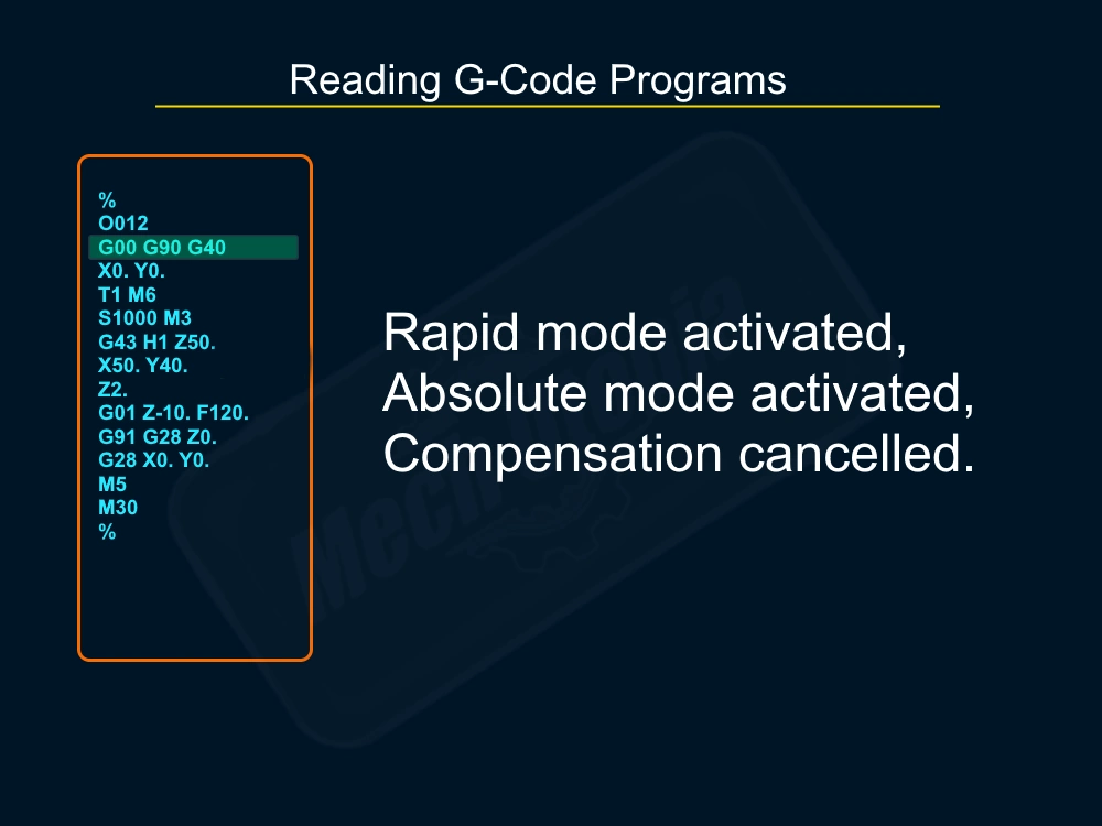
G00 G21 G90 G49; (This is the preparation line, we are setting modes of the machine)
T1 M6; (Tool Changing Line)
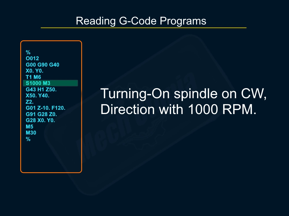
S1000 M3; (Spindle commands)
G43 H1 Z100. T2; (Tool offset settings and preparing the next tool on the carousel)
G01 Z0. F1000.; (feeding to plunge point)
(-This area will be your geometrical G-Codes which give the shape of your part.-)
M5 (Turning of the spindle)
G91 G28 Z0. ; (Sending Tool to home position)
G28 X0. Y0. ; (Sending workpiece to home position)
M30
% (Every G code program must start with the % percentage symbol)
Each line of G-code represents a command, comprising distinct letters and numbers that carry individual significance. For instance, the letter ‘G’ and ‘M‘ is often followed by a number to indicate a specific operation, such as G00 for rapid positioning or G01 for linear interpolation.
“%“, “; “, and “O” has a special purpose, they are kind of constant and you must use them as needed. For example “%” sign must be used to tell Program is starting, and a semi-colon “; ” must be used to end a line so the machine can progress further lines. And “O” must be used before declaring the program number ex. O0012. “12″ on here is my program number but it can be any number.
Understanding G-code is not just about memorizing commands, though. It’s about visualizing the machine’s movements, picturing how each command translates into physical action. G-code involves grasping its underlying logic, the sequence of operations, and the interaction among various commands.
Reading G-Code Commands
The CNC controller reads the programs from top to bottom. So we should start reading from the top always. While reading we should move the tool in our imaginary world. Kind of you need to simulate your brain and imagine the possible movements code can cause.
For instance, a command like G01 X10 Y20 Z30 F1500 tells the machine to move in a straight line to the point (X10, Y20, Z30) at a feed rate of 1500 mm/min.
The key to reading G-code is understanding the meaning behind each letter and number. ‘G’ and ‘M’ commands are primary functions that set the mode of operation. ‘X‘, ‘Y‘, and ‘Z‘ denote positions along the respective axes. ‘F‘ sets the feed rate, and ‘S‘ controls the spindle speed. Each command, each character, plays a crucial role in the symphony of operations.
Examples of G-Code Commands and Their Functions
Let’s take a closer look at some common G-code commands and their functions:
- G00: Rapid positioning. This command moves the machine as quickly as possible to the specified position. It’s like telling the machine to “hurry up and get to this point”.
- G01: Linear interpolation. This command guides a linear movement of the machine, creating a straight path between two points while simultaneously cutting the material during the process.
- G02 and G03: Circular interpolation. These commands move the machine in a circular path, with G02 for clockwise motion and G03 for counterclockwise.
- G20 and G21: Unit selection. G20 sets the units to inches, while G21 sets them to millimeters.
- G90 and G91: Absolute and incremental positioning. G90 tells the machine that all coordinates are relative to the origin, while G91 makes them relative to the current position.
- G41 and G42: These G-Codes used to set the cutter compensation side.
- G28 and G30: Returning to the home position, tool changing position.
In G-code, the letter “P” is often used to denote a parameter or a pause. For example, in dwell commands, “P” can represent the dwell time, indicating how long the machine should pause in a certain position. At the same time high precision machining command “G08 P1” uses “P” as a parameter.
“U” and “W” are often used as incremental coordinates parallel to the X and Z axes, respectively. “U” is used for horizontal movements. “W” is used for vertical movements. Utilizing “U” and “W” in conjunction with absolute coordinates (X and Z) enables machinists to execute complex and intricate operations with high precision.
Using G28, G30 Home Returning Commands
One of the things you will do most often while operating a CNC machine is sending it to Home. Sending home is just a metaphor we use for it. We actually sending the machine to the X0.Y0.Z0. position on its machine cartesian coordinate system.
Do not mix this with the datum and zero points used for the machining part. The main difference between part zero and machine zero is that we can overwrite part zero but we cannot change the machine zero. Just technical service can change it.
In the below animation, you see how a CNC machine returns home safely.
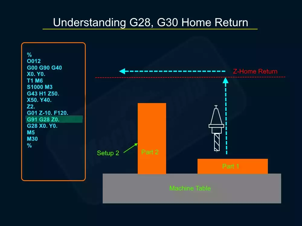
Always send the Z axis to the zero home position. In this way, you will not crash into other parts mounted on the table. So you should use these codes;
G91 G28 Z0. (Setting incremental mode to avoid CNC moving to part zero before moving to machine zero)
G28 X0. Y0. (Sending X and Y to home position)
You may have difficulty understanding G91, let me explain it. If you don’t use G91 then the CNC machine will be instructed to return to the Z home position, then the Z axis will move to the first part`s Z0. (which is the top of the workpiece).
This will give you a heart attack. Later it will return to machine Z0. position. So, to eliminate this dangerous movement we use G91 before it. After setting the mode to incremental system machine will not make a move down, it will simply just go up, the same for the X, and Y axis. Because we activated G91 one time we don’t need to activate it again. So just with G28 X0. Y0. machine can return to X, Y home zero position without moving to part`s zero datum point.
G30 is a standard code for the sending machine to the tool changing position. In milling, you can use G30 to send the Z-axis to send home, in turn, it is a turret tool changing position. The good thing with this you don’t need to worry bot the G91 incremental mode-changing process before using G30. But it is just working for Z-axis and cannot be used with X, Y axis.
For example;
G30 Z0. (Setting incremental mode to avoid CNC moving to part zero before moving to machine zero)
G91 G28 X0. Y0. (Sending X and Y to home position)
G-Code in CNC Milling and Turning
G-code holds a pivotal role in two widely used operations within the realm of CNC machining: milling and turning. These operations are highly prevalent in the field, and G-code is instrumental in executing them effectively. Whether it’s a 3-axis milling machine carving out a complex aerospace part or a CNC lathe spinning a piece of metal into a precise cylindrical shape, G-code is the conductor orchestrating every move.
In CNC milling, G-code commands control the movement of the cutting tool along the X, Y, and Z axes. G-code commands dictate several crucial aspects of milling and turning operations. Lines of G-code define various aspects of the machining process, such as the tool’s path, the depth of cuts, and the speed of tool movement. Whether it involves simple 2D shapes or machine 3D surfaces, every intricate detail is meticulously described within the lines of G-code.
Turning, on the other hand, involves rotating the workpiece while the cutting tool moves in a linear path. Despite the different nature of the process, G-code is still the language of choice. It controls the speed of the workpiece’s(round bar) rotation, the movement of the cutting tool, and the precise timing of tool changes. Some M-Codes can be different on CNC turning.
G-Code and the Cartesian Coordinate System
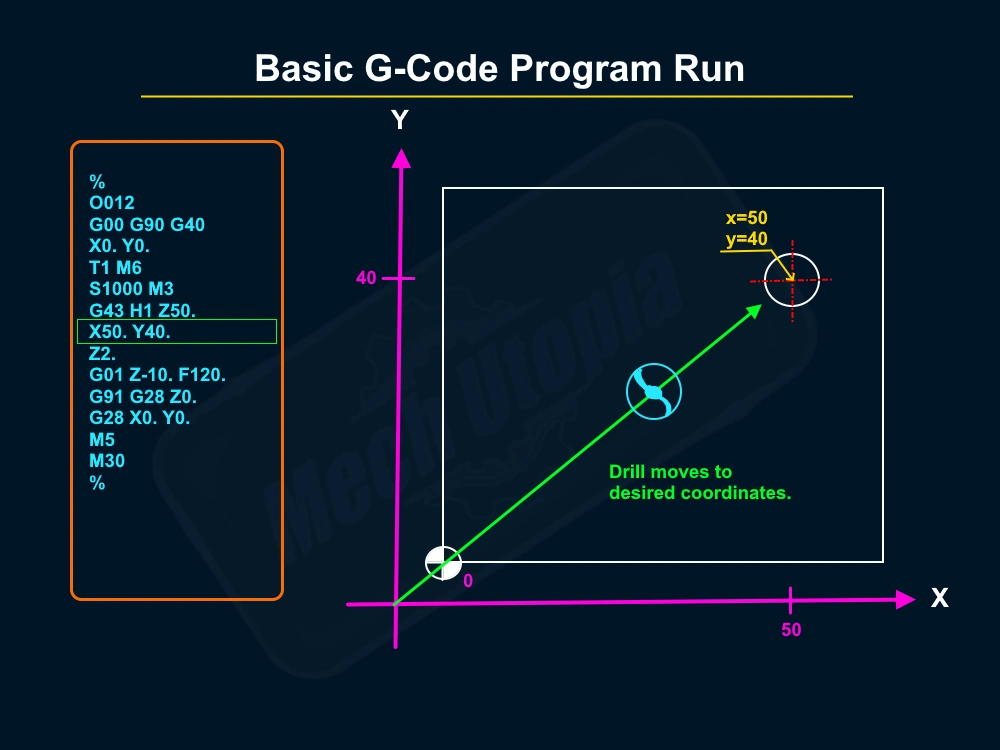
The Cartesian coordinate system is the foundation upon which G-code operates. The system, consisting of the X, Y, and Z axes, establishes a framework for precisely defining the cutting tool’s position relative to the workpiece. This framework enables accurate and controlled machining operations.
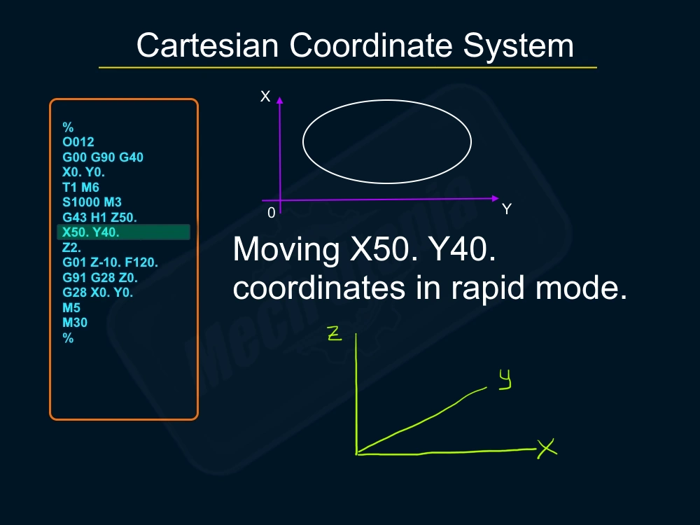
Each G-code command specifies a position in this three-dimensional space. For instance, a command like G01 X10 Y20 Z30 tells the machine to move the cutting tool to the point where X is 10, Y is 20, and Z is 30. This point is defined relative to a reference point, or origin, typically the corner of the workpiece or the machine’s home position.
The beauty of the Cartesian coordinate system lies in its simplicity. It provides a straightforward way of defining positions in space, which is crucial for the precise movements required in CNC machining. By using G-code commands to control the machine’s movements within this coordinate system, CNC machinists can craft parts with incredible precision and complexity.
Tool Compensation with G-Code
In the CNC machining industry, precision is worshiped. Every millimeter, every fraction of a millimeter, counts. That’s where tool compensation comes into play. This feature of G-code allows the machine to adjust for the physical dimensions of the cutting tool, ensuring that the part is machined accurately regardless of the tool’s size.
Tool compensation is significant when changing tools during a job. Different tools have different diameters, wears, and shapes. Without compensation, the machine would continue to cut as if the original dimension was still in place. Think like this; CNC machines already work with high accuracy a small amount of tool wearing can change the precision of a part.
Because your program is not changed according to wearing happens on your tool(new generation machines have special sensors to adjust compensation automatically ( keep in mind, this technology is still not available for most CNC Shops.)
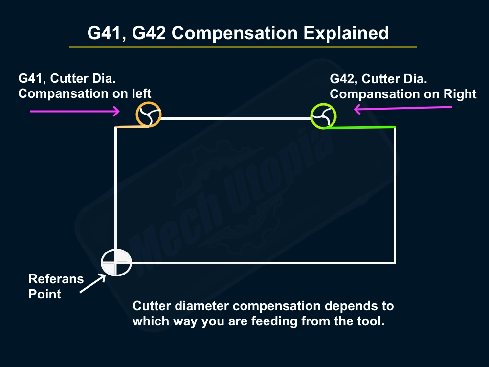
G-code commands like G41 and G42 are used to activate tool compensation. G41 compensates to the left of the tool’s path, while G42 compensates to the right. If you use G40 you cancel any compensation so the controller will follow the same coordinates without adding a radius. By incorporating these commands into the G-code program, CNC machinists can ensure that their parts are cut accurately, every time.
Reasons to use G41-G42 cutter compensation.
- Fine adjustment of critical tolerances like Helically bored bearing holes.
- Eliminating stress caused dimensional failure like cutting heavy passes.
- Elimination of the machine`s positioning capabilities caused by the controller. Servo motors can miss the true positions.
- Eliminating mechanical errors like looseness on ball screws. Because lack of a feedback system Open-cycle controllers cannot find and eliminate real-life mechanical errors.
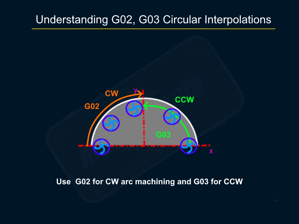
Understanding Circular Interpolation G02-G03
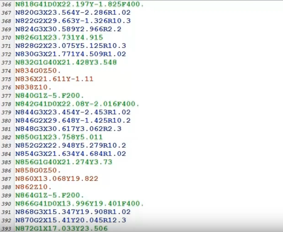
G02 and G03 are crucial G-codes in CNC machining. G02 is used for circular interpolation in a clockwise direction, directing the CNC machine to create arcs and circles with precision. This code necessitates the specification of the arc’s endpoint and the radius or defining it using “I” and “J” for the offsets.
G03, on the other hand, is the counterpart of G02 but operates in the counterclockwise direction. It functions similarly to G02 but offers the option of moving in the opposite direction.
Both G02 and G03 require careful management of the feed rate, as going too fast or too slow can negatively impact the machining process.
N10 T1 M06; (Select tool 1 and perform a tool change)
N20 S5000 M03; (Start the spindle at 5000 RPM)
N30 G00 X0. Y0. Z5.; (Rapid move to safe Z above the hole location)
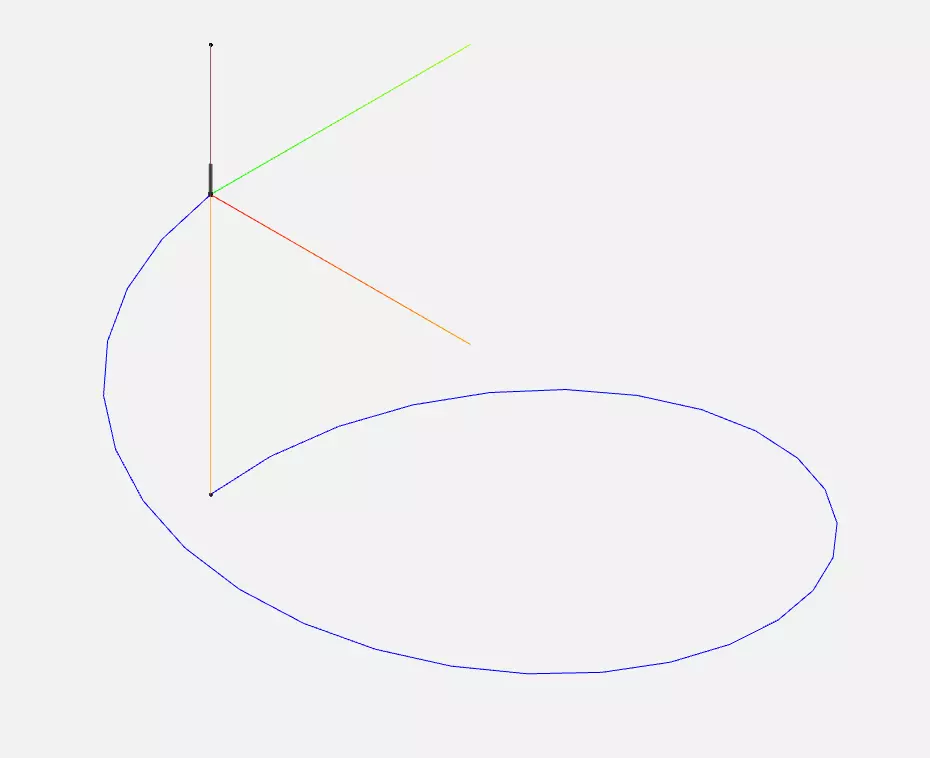
N40 G01 Z0. F100; (Feed to Z0 at a rate of 100mm/min)
N50 G03 X0. Y0. Z-10. I10. J0. F200 ; (Helical move down to Z-10 with a 10mm radius at 200mm/min)
N60 G00 Z5.; (Rapid move back to safe Z)
N70 M05; (Stop the spindle)
N80 M30;
Ultimately, G02 and G03 are fundamental tools for a CNC machinist to create precisely curved pieces, and mastering their use is an important skill in the field.
G-Code Program Line numbers
Probably you caught N10, N20. “N” stands for “Number“. They are line numbers and they do not affect anything on the toolpath and machine movement. It is just a markup for us to find and memorize the position of specific lines. It is very convenient when you need to between lines and just run a program below it. Also, this makes the easier debugging process.
CAD/CAM Softwares And G-Code Generation
CAM software serves as a useful tool in the arsenal of CNC machinists, enabling them to enhance their capabilities and productivity. It allows for the creation of complex 3D models and the generation of the G-code programs needed to machine those 3D models.
G-code and CAM software work hand in hand. The machinist uses CAD software to design a part, specifying the dimensions, and the type of material, and then the machinist switches to a CAM system to generate machining operations to be performed. The software then generates the G-code program that instructs the CNC machine on how to make the part.
Manual G-Code Programming
You may think that why we need CAD/CAM system if we can write manually G-Code programs. You need to use CAM software to generate very complex programs for complex parts. From my experience, I found out manual G-Code writing is good if you just need a short 2.5 Axes program. Otherwise, it gets very complicated.
While CAM software has made it easier to generate G-code programs, there’s still a place for manual G-code programming in the world of CNC machining. Understanding how to manually write and edit G-code can give you a deeper understanding of how CNC machines operate.
Manual G-code programming involves writing each line of code by hand. It’s a process that requires an understanding of G-code commands and a keen eye for detail. Each command must be carefully crafted to guide the machine’s movements and ensure the part is machined accurately.
Advantages of writing Manuel G-Code CNC programs.
- Writing short programs are easier and faster than programming with cad/cam software.
- You don’t need to deal with 3D solid models and complex engineering drawings and drafts.
- You can finish the whole programming on the embedded CNC code editor in the controller.
Disadvantages of writing Manuel G-Code CNC programs.
- Programming complicated parts are hard and take a long time
- You must need to create a perfect program in your mind otherwise you can crash easily the CNC machine.
- Debugging is getting harder, and changing can break another part of the program.
Despite the advantages of CAM software, I’ve found that manual G-code programming is still a valuable skill. Mastering G-code provides enhanced control over the machining process, proving invaluable in troubleshooting and resolving issues effectively. Plus, there’s something deeply satisfying about crafting a G-code program by hand and watching as the machine brings your vision to life.
Tips for writing Manuel G-Code CNC programs.
- Planning: Make sure you have planned all with cut, plunging depth, feed rates, speeds, etc.
- Calculations: Calculate contours, tool turning center points, linear interpolations, and circular interpolations.
- Optimizing: Always prefer canned cycles, these cycles will decrease your handwritten codes and maximize efficiency.
- Verifying: After running your manual written G-Code program make sure you tested and verified it on your G-Code Simulator. In this way, you can eliminate crashing risks.
- Debugging: If you have any debugging problems with the G-Code program, look for the semi-colon (end of line), and decimal point typing mistakes.
- Using Dot: Use a dot on the and of every number declaration. if you don’t use dots some machines can accept in micrometers, not in millimeters. For example, use “X5.” instead of “X5“.
Troubleshooting G-code Errors
You can hit a G-code error easily when you write manually. Below the list, you can see commonly encountered examples and solutions of them.
- “Unkown G-Code”: If you get this error it means you are using a G-Code not supported by your machine. Or it is possible that you had a typo while writing them. Check your machine`s guide to verify the G-Code.
- “G32 Cannot Cycle“: This error often happens when you stop the program in the middle of a drilling cycle. To clear it you need to go MDI mode and cancel the cycles with G80.
- “G02 -G03 Arc Cannot Find Ending Point”: Some post processors can output G-Codes for A, and B axes even machines don’t have them. Mostly you will not get errors until you send those axes to the home position. To avoid it just delete A0. B0. G-Codes from your G28 lines.
| G-Code | Description | Possible Parameters |
|---|---|---|
| G00 | Rapid positioning | X, Y, Z |
| G01 | Linear interpolation (Straight line move) | X, Y, Z, F |
| G02 | Circular interpolation (Clockwise) | X, Y, Z, I, J, K, F |
| G03 | Circular interpolation (Counterclockwise) | X, Y, Z, I, J, K, F |
| G04 | Dwell (Pause) | P or X |
| G09 | Exact stop check | None |
| G10 | Programmable data input | L, P, X, Y, Z |
| G17 | XY plane selection | None |
| G18 | ZX plane selection | None |
| G19 | YZ plane selection | None |
| G20 | Programming in inches | None |
| G21 | Programming in millimeters | None |
| G28 | Return to the secondary home position | X, Y, Z |
| G30 | Return to the secondary home position | X, Y, Z |
| G31 | Return to the secondary home position | X, Y, Z, F |
| G32 | Threading with a single-point tool | X, Z, F |
| G33 | Constant pitch threading | K, Z, F |
| G40 | Cutter compensation cancel | None |
| G41 | Cutter compensation left | D |
| G42 | Cutter compensation right | D |
| G43 | Tool length compensation positive | H, Z |
| G44 | Tool length compensation negative | H, Z |
| G49 | Cancel tool length compensation | None |
| G53 | Machine coordinate system | None |
| G54 | Workpiece coordinate system 1 | None |
| G55 | Workpiece coordinate system 2 | None |
| G56 | Workpiece coordinate system 3 | None |
| G57 | Workpiece coordinate system 4 | None |
| G58 | Workpiece coordinate system 5 | None |
| G59 | Workpiece coordinate system 6 | None |
| G61 | Exact stop mode | None |
| G64 | Cutting mode | P |
| G73 | High-speed peck drilling cycle | R, Z, Q, F |
| G76 | Fine boring cycle | Z, R, P, Q, F |
| G80 | Cancel canned cycle | None |
| G81 | Simple drilling cycle | R, Z, F |
| G82 | Counter boring cycle | R, Z, P, F |
| G83 | Peck drilling cycle | R, Z, Q, F |
| M-Code | Description | Possible Parameters |
|---|---|---|
| M00 | Program stop | None |
| M01 | Optional program stop | None |
| M02 | End of program | None |
| M03 | Spindle start (clockwise) | S (speed) |
| M04 | Spindle start (counterclockwise) | S (speed) |
| M05 | Spindle stop | None |
| M06 | Tool change | T (tool number) |
| M07 | Coolant on (mist) | None |
| M08 | Coolant on (flood) | None |
| M09 | Coolant off | None |
| M13 | The spindle on (counterclockwise) with coolant on | S (speed) |
| M14 | The spindle is on (counterclockwise) with coolant on | S (speed) |
| M19 | Spindle orientation | None |
| M21 | Mirror image X-axis on | None |
| M22 | Mirror image X-axis off | None |
| M23 | Mirror image Y-axis on | None |
| M24 | Mirror image Y-axis off | None |
| M30 | Program end and reset | None |
| M98 | Call subprogram | P (program number), L (number of repeats) |
| M99 | End of subprogram | None |
Conclusion
G-code is the lifeblood of CNC machining. It’s the language that guides the machine, the roadmap that transforms a raw piece of material into a precisely crafted part. Whether you’re an experienced CNC machinist or a beginner taking your first steps, mastering G-code is of primary importance.
From understanding the basics of G-code to delving into the intricacies of tool compensation and manual programming, the journey of learning G-code is a rewarding one. My journey in CNC machining has spanned several years, and it continues to bring me immense joy and fulfillment. So, whether you’re programming a complex 3D part or simply drilling a hole, remember – it all starts with G-code.