In this article, I will delve into the process of cutting metal parts from thin plates using CNC machines. Often, we need to extract parts from metal plates, which might be the only material available or chosen for its ease of use. A challenge arises when these plates have standard thicknesses, such as 10mm (0.394 inches) or 12mm (0.472 inches). This makes it difficult to machine the part if its final thickness is the same as the plate. While you can touch the top with a face mill for surface cleaning, many of our customers prefer to avoid any facing operations.
- Cutting Strategy
- Monitoring cutting operation
- FQA
- What challenges arise when cutting from plates with standard thicknesses?
- What is the recommended method when the stock thickness and final part thickness are identical?
- How can contours be effectively cut?
- Why are two different sized endmills used for cutting?
- What precautions should be taken regarding health and safety while cutting metals with CNC?
- What are some craftsmanship challenges faced during this process?
- Which material was used in the example provided in the article?
- How does material hardness affect the cutting process?
- Summary
For those familiar with CNC Machining, you’ll recognize a standard method: starting with a thicker stock than needed. For instance, if you have a 15mm (0.591 inches) thick material and your final part needs to be 10mm (0.394 inches) thick, you can use the 5mm difference to hold the part in a vise for a second operation, finishing it with a face milling operation.
However, what if your stock thickness and final part thickness are identical? In such cases, we opt for a different approach. Given the specific cutouts in the plates and their thin nature, it’s most practical to hold these parts from the side.
Cutting Strategy
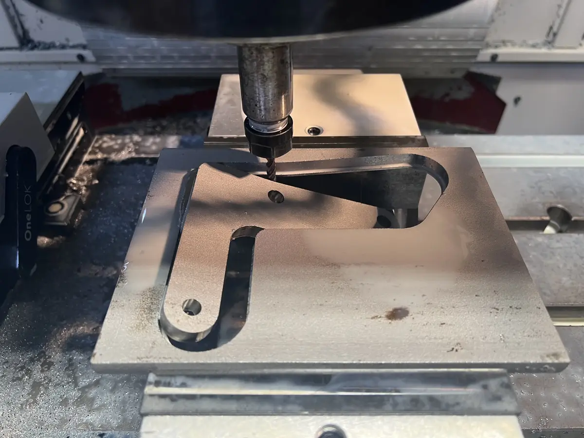
I found from my experience cutting to contours can be achieved with ramp-contouring toolpaths very well. Ramping style toolpaths support and eliminates tool breakage. This happens by plunging while cutting, so there will be a push towards the Z+ axis to support the spindle and cutting tool. In our case, we use carbide endmills.
From the below list, you can see the proper steps of how to cut parts from the metal plate;
Preparation:
- Select the appropriate metal plate, considering its thickness.
- Ensure the CNC machine is calibrated and ready for operation.
Understand the Challenge:
- Recognize issues with standard plate thicknesses, such as 10mm or 12mm.
- Determine if the final part’s thickness matches the plate’s thickness.
Setting Up the Machine:
- Position the metal plate securely.
- Choose the right endmill size; start with a 10mm endmill.
Cutting Strategy:
- Implement ramp-contouring toolpaths for effective contour cutting.
- Avoid plunging to the final depth immediately; work in stages.
Safety Measures:
- Always close the CNC machine’s safety doors before starting.
- Wear protective gear to prevent injuries from flying metal parts.
Monitoring and Adjustments:
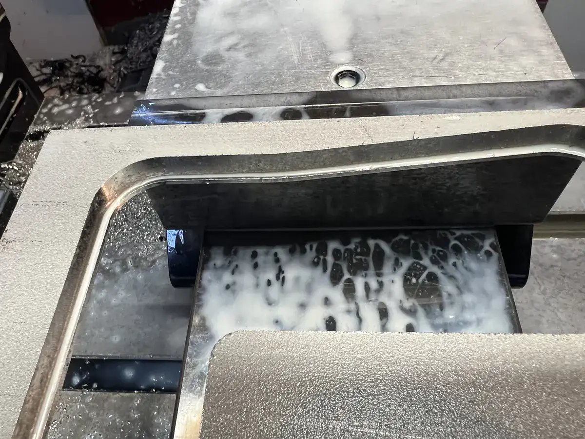
- Keep an eye on chip evacuation to ensure a smooth surface finish.
- Adjust feed rates as necessary for optimal cutting.
- Pause the machine if you notice any irregularities.
Finalizing the Cut:
- Use a smaller 6mm endmill for the final cut to ensure precision.
- Ensure the side surface of the part remains undamaged.
Post-Cutting Process:
- Remove the cut part carefully from the machine.
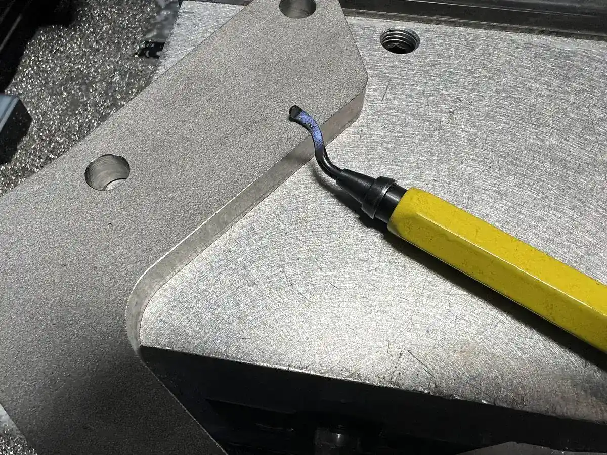
- Finish the edges with a belt grinder for a smooth finish.
Using Endmills to cut-out profile of parts
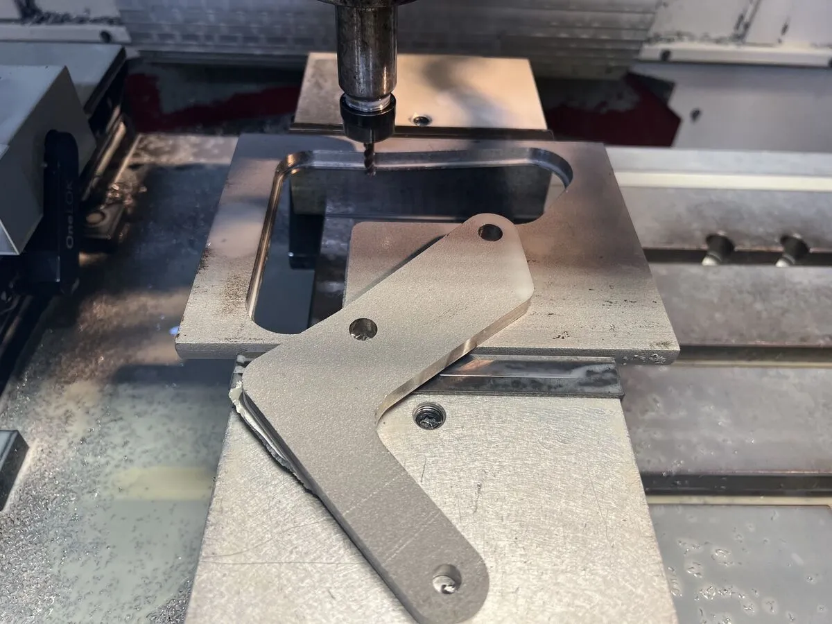
I have used 2 endmills to cut just the profile of the part from blank stock. one is a 10mm Endmill other one is a 6mm Endmill. You may ask yourself why we just don’t finish the whole job with one Endmill cutter. It is possible but you always can harm the side surface of the part. We use the first larger cutter (10mm Endmill) to give room for the final cutting with a smaller cutter(6mm Endmill).
Managing the cutting depts and final depth
As you can guess we shouldn’t plunge till our final cutting depth. Otherwise, you will finish cutting out the mission with one tool and it can push the parts to the side walls of part and stock. If our metal plate is 10mm thick then we need to ramp-contour to -9mm thickness so this last 1mm layer will hold the part to cut the final shape with 6mm endmills. Smaller cutters will have less cutting stress so we can just plunge the final depth+extra tear depth. in our example 10mm+1mm = 11mm.
Monitoring cutting operation
As I said before cutting like this is a very fast and efficient way to finish jobs very fast with our second operation setup. However, it brings its own special safety and skill challenges.
Health and safety challenges while cutting out metals by CNC
In our example, you need to always close the safety doors and coverage of the CNC machine because cut parts are free and they can be thrown around by the spindle.
Craftsmanship challenges
You need to stop the machine and decide to decrease feed rates where necessary otherwise you will break the cutter. Because on the final pass, parts will be free to move. Also, you need to manage chip evacuation to have a nice surface finish and keep the tool alive. A super finish contouring can give a good surface finish, just put it between the first and last final operation.
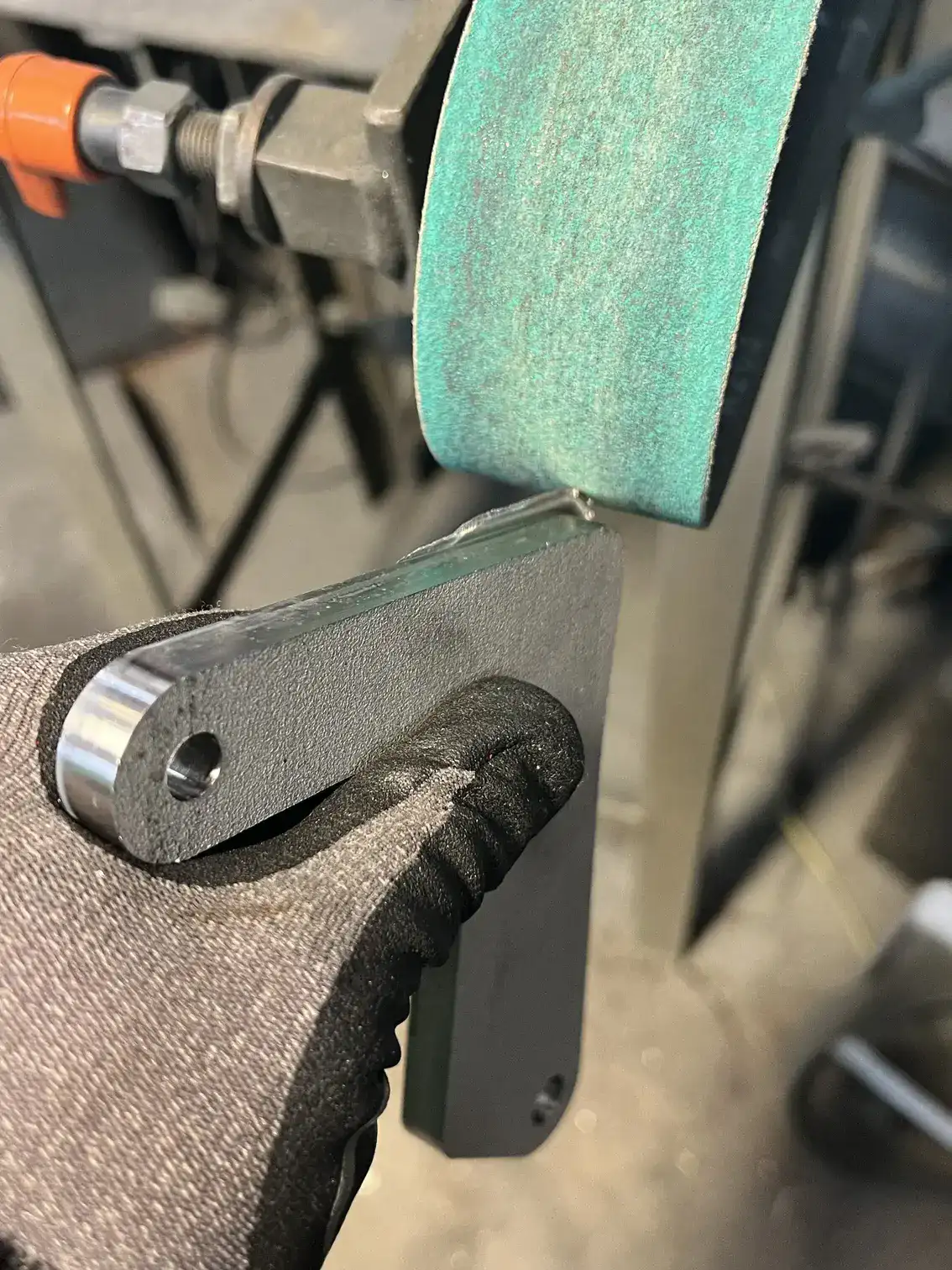
As you can see in the above picture you need to finish with belt grinder edges properly.
Material Preferences
In this example, I have used Stainless steel due to the customer`s requirement. Normally hard materials like stainless steel are challenging, however, this time hardness turned out to help with the rigidity. Let me explain; When you squeeze a metal plate between vise jigs the plate generally tends to get a convex shape due to the pressures on the side.
Yes, you guessed correctly, because of the hardness of the material I could apply plenty of power to hold it properly flat with vise. This allowed me to move after the contour machining operation and kept the frame safe till the end of the cutout operation.
So it is logical to think that if you have a softer material like Aluminum and Brass plates you should apply less squeezing force on the vise to eliminate the plate from getting a convex shape. If you machining loosely hold plates on a vise then you should select conservative feeds and speeds to cut parts without releasing from jigs.
FQA
What challenges arise when cutting from plates with standard thicknesses?
A challenge arises when these plates have standard thicknesses, such as 10mm or 12mm. It becomes difficult to machine the part if its final thickness is the same as the plate.What is the recommended method when the stock thickness and final part thickness are identical?
In such cases, given the specific cutouts in the plates and their thin nature, it’s most practical to hold these parts from the side.How can contours be effectively cut?
Contours can be achieved with ramp-contouring toolpaths. Ramping style toolpaths support and eliminate tool breakage by plunging while cutting.Why are two different sized endmills used for cutting?
A 10mm endmill is used first to give room for the final cutting with a smaller 6mm endmill. This approach ensures the side surface of the part is not harmed.What precautions should be taken regarding health and safety while cutting metals with CNC?
It’s essential to close the safety doors and coverage of the CNC machine because cut parts can be thrown around by the spindle.What are some craftsmanship challenges faced during this process?
Operators need to manage chip evacuation for a good surface finish, stop the machine and adjust feed rates when necessary, and finish with belt grinder edges properly.Which material was used in the example provided in the article?
Stainless steel was used in the example due to the customer’s requirement.How does material hardness affect the cutting process?
Hard materials like stainless steel provide rigidity, which can be beneficial. However, softer materials like Aluminum and Brass require different considerations, such as applying less squeezing force on the vise.Summary
As you can see this is a very efficient method to cut out parts from metal plates. Also, these techniques can be applied to plastics and wood. Also, this can be a good solution when you cannot send parts to water jet cut and laser cut. Elimination second operation also saves a soft just set for you.