Introduction
Computers are a big part of modern life and in this age of Computer Aided Manufacturing (CAM). Computer-Aided Manufacturing (CAM) is making easy to plan and monitor the manufacturing process. This can be either directly(DNC) or indirectly(NC), by creating a computer interaction field between the production resources of a manufacturing facility. With Computer-Aided Manufacturing (CAM), we can machine parts faster and better.
CAM programs were not very common in the past, but they have become very important now. CAM programs are programs that use the parameters you give them to make NC codes that CNC machines can use to process parts that are hard to write by hand, or even impossible to write by hand. CAD and CAM modules are now part of the same package, which makes it easier for companies to work on the same data and meet their needs. In the past, CAM programs were written separately from CAD programs.
History of Computer-Aided Manufacturing (CAM)
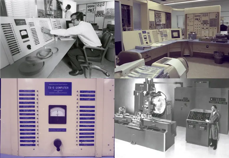
In 1946, John T. Parsons and his team made the first milling machine that was controlled by a computer. This machine was used to make the complicated shapes of helicopter blades. In 1952, Parsons tried to get a patent for this technology. In 1958, he got a patent called “Motor Controlled Apparatus for Positioning Machine Tool,” which was later changed to Numerical Control (NC).
In 1952, the US Air Force gave MIT a project to figure out how to make hard-to-make ballistic parts automatically. Researchers at the university were able to make these parts automatically by making a machine called a “milling machine”. After 1970, CNC benches were used that put the work of electronic circuits on a small number of microprocessors. By combining Computer Numerical Control (CNC) and Programmable Logic Controller (PLC), all kinds of manufacturing and putting things together can now be done by computer.
Silicon Valley used the fact that CAD/CAM systems aren’t good for mass production to make microprocessors and chips. So, computers that were too expensive to buy became very cheap, and their size got just right by getting smaller. It began to be used in making molds, electronics, machinery, and many other fields. Over time, CAM software has been getting better and better.
What Is The Importance Of CAM?
In the field of production, the goal of computer technology is to bring together engineering and running tasks under one roof. Using commercial data processes, computer-aided production also helps take orders, make material inputs, and plan production around these things. The main things that affect the production system are changes in technology.
Computer-aided systems and computer-integrated production systems have been made for product development, product design, production planning and control, collection of production-related data, and maintenance functions in businesses. Here are some of the modules that make up Computer Integrated Manufacturing Systems. When these modules are put together, a Computer Integrated Production System is made.
In Which Fields Is CAM Used?
We can say that making a field limitation for CAM is almost impossible. CAM has a structure that, whether it works or not, can give the user exactly what they want if they use the right machining benches. But, with the help of CAM, mass production is done in the auto industry, in making airplane parts, in making robots, and in many other fields.
Where Do We Need CAM?
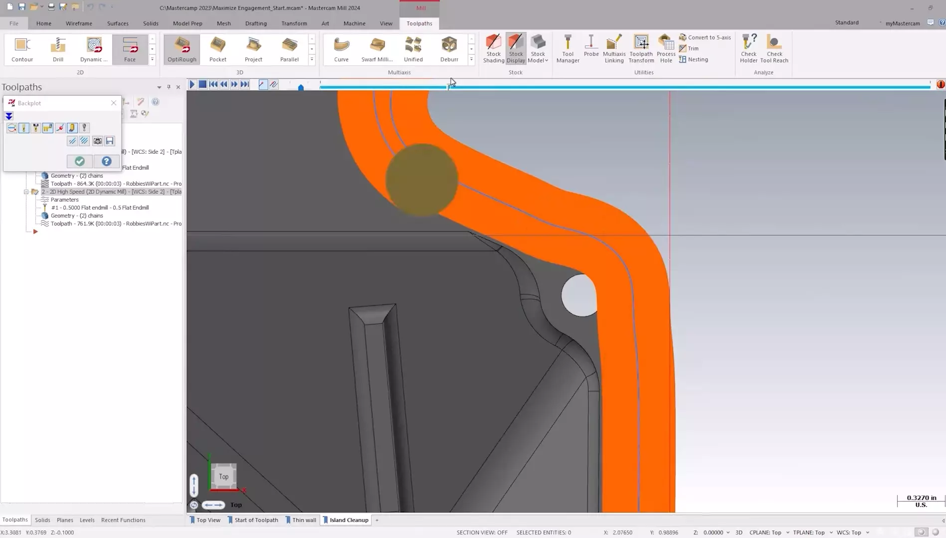
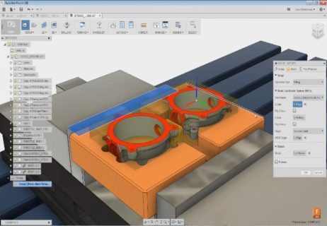
To machine a CAD part, you need a machine language that a milling machine or lathe can understand, and you also need CAM software. People often call this language “G-Code.” Before a CAD model can be turned into this machine language, the CAM software must be programmed to figure out the cutting paths that the tools will use to remove excess material and make a part. Most CNC Milling, CNC Lathe, and CNC Router have it. It is also used in the part programming process for CNC Water Jets, Plasma, Laser, and CNC Burners.
CAM software tells these tools where to cut and how fast and far they should move. CAM software lets the operator enter tool data or choose a tool from a library within the software, manage materials, and make an optimized toolpath for machining the CAD part model.
There are a lot of different things to talk about when it comes to CAD-CAM toolpaths because there are so many different ways to use toolpaths in different machining situations. But programmers also commonly use drilling, 2D toolpaths, and 3D toolpaths. There are different ways to use these toolpaths, such as profiling, pocketing, skinning, engraving, 3D contouring, and more.
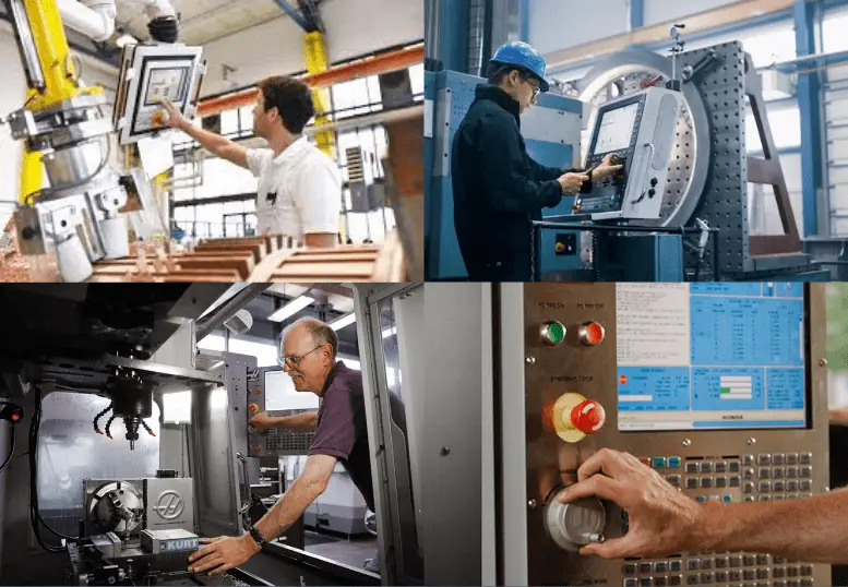
Many different kinds of CNC machines are used to make mechanical parts. You can also turn manual machines into CNC machines by adding a motor, CNC controller, and other important parts. In a so-called “Finisher” method, the CAM software translates the machining toolpath and any other information into the style of NC Code that a certain machine tool can understand. Most of the time, the operator or a CAD-CAM technician can change how these post-processors work. Either way, it is part of the process of programming a CNC machine.
What Are The Benefits Of Using CAM?
The biggest benefit is that it is fast, and compared to human hands or work, it takes less than 1% of mistakes. For example, a product that takes two days to make by hand on a standard processing machine can be made more smoothly and perfectly in 45 minutes with the help of CAM.
CAM is also helpful because it gives users control in real-time. During the production phase, the operator can step in wherever he wants and run the machine more efficiently with the help of the software changes he has made.
What Are The Disadvantages Of CAM?
- We need people with a lot of skills. Workers who do CAD and make CAM systems need to be highly qualified and trained, and they probably make a lot of money.
- Employees being let go. CAM will put a lot of people out of work, which is an ethical or corporate social responsibility issue for the business.
- Installation takes a long time and costs a lot. CAD and CAM require a lot of money to set up because they use expensive software and robotics. This means that many businesses can’t use them.
This table shows the advantages and disadvantages of computer-aided manufacturing (CAM)
| Advantages of Computer Aided Manufacturing (CAM) | Disadvantages of Computer Aided Manufacturing (CAM) |
|---|---|
| The production process doesn’t need much supervision and can be done at any time. |
It takes a lot of money and time to get started. |
| Production requires less labor and saves labor cost. | Taking care of machines costs money as well. |
| The machines are accurate, and large batches can be made over and over again in the same way. |
It can lead to the loss of workers who are really skilled with their hands. |
| Errors happen very rarely, and the machines can run without stopping. |
To make sure that the tools are used and adjusted correctly, it needs operators and technicians who are very well trained. |
What Do CAD & CAM Programs Do?
CAD and CAM programs help businesses make a lot of money when they are used in production. CAD programs help the designer draw quickly, and the fast and useful toolbars in the programs make it less likely that the designer will make mistakes. With CAM programs and the use of computers in production, the speed of production is many times faster than with old methods. For example, when using the traditional method of turning, a simple piece can be made twice per hour. However, when the same piece is programmed with CAM, the CNC lathe can make 20 pieces per hour.
Computer-aided design is used in many programs today. Even though most of these are different, there are some programs that are widely used and easy to find on the market. AutoCAD, SolidWorks, and CATIA are some of the best CAD programs. With these programs, you can make designs in two dimensions or three dimensions, depending on what you want to do. For example, a piece that will be made from a metal sheet needs a two-dimensional design, but a three-dimensional piece that will be made from steel needs a three-dimensional design.
Computer-aided production benches like CNC need a set of instructions on how to process a design made with a CAD program in order to make that design. With the help of CAM programs, CAD drawings made with CAD programs are turned into the final product.
Most of the time, CAD programs save designs as a file type that is unique to that program. Even though many programs, like Parasolid, support common extensions, the best program for CAM is one that works well with CAD. For example, the standard file extension for an AutoCAD drawing is dwg, so a CAM program that can work with dwg files would be a good choice.
MasterCAM, SolidCAM, CamWorks, TopSolid, and EdgeCAM are all CAM programs that are often used for computer-aided production. Aside from these, there are many other programs that are used for CAM. The best way to choose a CAM program is to take into account both the designer’s and the product’s needs.
With the widespread use of computer-aided production, there are packages that include both CAD and CAM programs to get rid of compatibility issues and other problems that can happen during the CAD and CAM stages. With programs that can do both jobs at once, the manufacturing process is faster and more useful.
Siemens NX and CATIA are the most popular CAD/CAM programs in the Aerospace industry, the powerful design and production tools that these two programs offer to their users make them very popular. The Microsoft Windows operating system is the only one that works well with CATIA, Solidworks. The Siemens NX program, which is also called Unigraphics NX, works with both.
Windows and Mac operating systems. At the design stage, both programs have tools that let you use many static and dynamic analysis methods, such as the finite element method, to build your design. So, CAD/CAM software helps to show, simulate, and analyze a part in its entirety in a virtual environment while it is being made, and it also does the last step for the finished product. You can get the shape you want by sending it to high-tech CNC machining benches.
With technological improvements in web technologies, nowadays CAD systems can be delivered from web browsers in 3D. The companies like On-Shape invented the first cloud-based browser-compatible CAD software.
What Is The Link Between CAD & CAM?
Computer-aided design, or CAD, is a way to turn a basic idea for a product into a detailed engineering design. For CAD, you have to think about and analyze how to design a product, while for a CAM system, you have to control and coordinate the physical process, equipment, materials, and work.
Difference Between CAD & CAM?
Computer-aided engineering (CAE), which includes CAD and CAM, is a very important process. Both CAD and CAM have benefits that are similar, and they can show parts in 2D or 3D. Both CAD and CAM make it easier for scientists to quickly process and make any design they come up with. Most CAM machines come with CAD software already built in.
The end user is the most important difference between CAD and CAM. Most engineers use CAM software, while a trained machinist uses CAM. The skills of these machinists are the same as those of a computer engineer.
This table shows the differences between CAD & CAM
| DIFFERENCES BETWEEN | |
|---|---|
| CAD | CAM |
| CAD is a way to turn an idea for a product into a detailed engineering design by using a computer. It involves making geometric models of a product that can be changed, studied, and made better. |
CAM is a way to help managers, manufacturing engineers, and production workers by using computers to automate production tasks and control machines and systems. |
| CAD includes steps like defining the geometric model and translating the interface, designing and analyzing an algorithm, drawing, detailing, and finally documenting. |
CAM includes things like geometric modeling, numerical control programs, interface algorithms, inspection, process planning, assembly, and packaging. |
| For CAD, product design needs to be thought out and analyzed. | For a CAM system to work, the physical process, equipment, materials, and work must be controlled and coordinated. |
Summary
At final, as you can see that CAM systems are embedded in our modern life. CAM systems make everything easier about machining, so today we are more capable to make more complex parts. It produces G-Codes from solid models for every kind of CNC machine brand. Also, integration with CAD systems allows more complex manufacturing capabilities like fixture designing which is used heavily in the CNC machining industry.
Also, you can check this article about CAD system