3d Model Kit Downloadable Ready!
We may send you files via E-Mail.Follow the instructions please.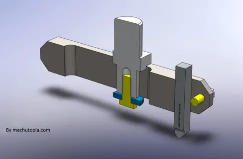
- Which Fly Cutter Should You Use?
- The Structure Of A Fly Cutter
- Stress Analysis Of A Fly Cutter Between 0 RPM And 1500 RPM
- Assumptions, Realities, And Scope Of The DIY Fly Cutter Project
- Snapshots From DIY. Fly Cutter Test
- How To Make DIY Fly Cutter?
- Summary
- FQA about the Fly Cutters.
- What is a fly cutter used for?
- What is the difference between a face mill and a fly cutter?
- How deep can a fly cutter cut?
- What is the advantage of a fly cutter?
- Can you cut a hole with a fly cutter?
- Is it better to use a fly cutter or face mill when milling steel?
- What speed do you run a fly cutter?
- How fast do you run a fly cutter?
- Is a fly cutter better than a face mill for surface finish?
- How do you use a fly cutter on a milling machine?
Fly Cutters some times a life-saving tool that gives you huge opportunities to finish jobs with high surface quality. Adjustable fly cutters easily can cut larger flat areas in one cut with high surface quality.
This article will be a tutorial that includes step-by-step explanations and FEA Stress Analysis of the Fly Cutter at varied spindle speeds.
As you can imagine, this excentric tool produced very high centrifugal forces at high speeds.
So we put it through an FEA analysis software(Solidworks), which will give us all the critical stress values of our fly cutter bits.
Which Fly Cutter Should You Use?
All Fly Cutters have some common characteristics like Adjustability, and cutting blade properties like indexable or fixed. Our one is an Adjustable Fly Cutter, also indexable cutting tips can be attached to it.
The Structure Of A Fly Cutter
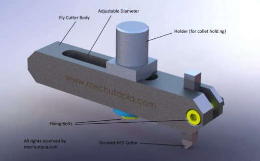
A basic Fly Cutter consists of a couple of Fly cutter components;
Component-1: Holder
Component-2: Fly Cutter Body
Component-3: Cutting Blade
Component-4: Fasteners
Stress Analysis Of A Fly Cutter Between 0 RPM And 1500 RPM
We are sharing our structural FEA analysis so you can see how the Fly Cutter body responds to high RPM. Our idea was to make a stress test to be sure the whole design concept was safe.
We are going to provide some snapshots of real-time stress calculations which will prove the importance of spindle speed while using fly cutters.
Assumptions, Realities, And Scope Of The DIY Fly Cutter Project
We are going to ignore the machine-specific configurations by keeping the reality in mind that all machines are in different configurations. So we have concentrated on our customized design for the fly cutter and its parts. We will never reach the level that will break down a CNC machine or milling machine.
Fly Cutters are not designed for heavy-duty cutting. Fly Cutters are commonly used for light cuts like surface finishing and so on. So naturally, we assume that there will not be a problem with cutting light passes. Check this guide to find our speeds and feed rates for a safe cut.
We selected spindle speeds for our snapshots: 500 RPM, 1000 RPM, and 1500 RPM. We selected those because they are realistic for a real-life usage scenario of a fly cutter.
1500 RPM can be the upper limit, but there is no harm in testing it in a computerized safe analysis environment.
Snapshots From DIY. Fly Cutter Test
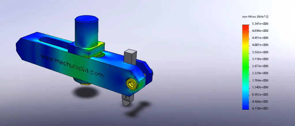
As you can see in the above figure how stress increases proportionally with spindle speed. When we spin faster the fly cutter produces more centrifugal forces. These forces directly will be transformed into the tool holder, spindle bearings, spindle housing and to chase off the milling machine.
There are no red segments on the FEA result, that is means we are good to go with these materials and dimensions. These tests are done under 1000 RPM and 1500 RPM. 1500 RPM is not a realistic usage scenario for fly cutters so I recommend do not go more than 1000 RPM, always starting with 500 RPM and increasing gradually if is everything ok.
How To Make DIY Fly Cutter?
After clarifying centrifugal stress distribution concerns, we are ready to manufacture your first Adjustable Fly Cutter. We are sure now it is safe and also very functional.
The figure below shows the inner view of the fly cutter. The cutting diameter is adjustable. You just need to undo the bolt and move the blade holder to the diameter you want.
If you have a CNC machine you can directly download our 3d Parasolid(.xt) file to make CNC programs with your CAM system. Also, there will be 2D mechanical blueprints for those who prefer to machine manually in a Milling machine and Center Lathe.
These files are very explanatory, so you will be able to fully understand the project plans. Also, now we are going to deep dive into a step-by-step guide.
[email_subscription]
Step 1: Machine the parts according to 3d Models and Blueprints
You need those steels and fasteners:
For Blade Holder: Cold drawn or hot drawn 25mm x 25mm x 150mm Mild Steel Bar ( imperial: 1inch x 1inch x 6inch ).
For Body Holder: AISI 1045 medium tensile steel 25mm x25mm x 60mm ( imperial: 1 inch x 1 inch x 2.4 inches).
For Cutting Blade: Standard 8mm x 8mm x 40mm HSS Bar (for cutting aluminum and plastics).
Washer: 8.5mm x 25mm x 5mm
M8x35 Bolt 1 piece.
M6x30 Socket Head Screw 1 piece.
Step 2: Grind the Fly Cutter blade (with correct angles)
Machine the parts according to mechanical plans.
You need to grind the cutting blade properly;
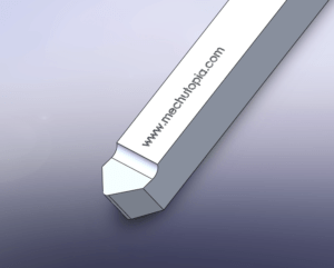
Keep the end radius of the blade bigger for harder materials, in contrast, you need to give a very less end radius (almost no radius) for softer materials. You need to check the grinding angles and dimensions from the 3d model.
Step 3: Assemble the machined parts according to the blueprints provided
Use fasteners to assemble the pieces.
Step 4: Put it into your Milling machine or CNC machine
It would help if you used a 22mm diameter collet with a BT40 tool holder ( for CNC machines ).
For conventional Milling Machines use a suitable holder for 22mm Dia. collet.
Optionally you can re-machine the 22mm Diameter shoulder to 20mm for holding the 20mm collet.
Step 5: Adjust the diameter of the Fly Cutter
You can adjust the diameter between 90mm facing Dia. and 150mm Dia.
In 90mm Dia. option Fly Cutter going to be naturally balanced due to its geometry.
While if you want to be bigger then you must start with very little spindle speed to avoid the danger of an unbalanced Fly Cutter.
Summary
In this article, I provide an explanation and tutorial on Fly Cutters, including a stress analysis at various spindle speeds, an overview of the fly cutter structure, and a step-by-step guide to creating a DIY fly cutter.
Fly Cutters are adjustable tools used for light and large flat-area cuts with high-quality surface finishes. My stress analysis demonstrates that spindle speeds up to 1000 RPM are safe for the fly cutter design, but I recommend starting at 500 RPM and increasing gradually.
The DIY guide outlines the materials and machining processes needed to create the fly cutter, as well as how to adjust the diameter for optimal performance.
Please check the project page…