In this article you will learn how control the program flow and simulate a CNC program in a CNC Lathe and CNC Mill.
Testing The Program
In CNC machines, programs are written according to technical drawings and taking into account geometric tolerances.
Therefore, it is almost impossible to write a very good program the first time, so CNC manufacturing technologies include simulation software for CNC machines and cad/cam systems.
Thanks to this software, the tool paths are tested in a digital environment before the machine goes into real cutting.
Checking The Program’s Logic and Spelling Errors
The most primitive method for humans to communicate with computers is to write code. Today, modern cad/cam systems and CNC machines hide low-level and hard-to-understand codes from CNC programmers.
Automatic postprocessor and code generators convert the final versions of the programs to g-code and M-code according to the specific CNC brand.
While this system ensures that errors are prevented almost from the beginning, it also prevents the flexibility of writing custom G-Code and M-Code.
So if a CNC programmer manually writes custom CNC codes and programs in an MDI mode, logical errors and code spelling errors are inevitable.
To debug your CNC programs and eliminate the CNC crash risks consider the below methods to find errors before the real cut.
- First, the program needs to be redesigned. This can sound hard but sometimes deleting old programs and writing every think again is easier than going up and done on MDI Mode.
- The second option is to use simulation software or a CNC controller embedded in the machine. These days this option is mostly the preferred method. Today some CNC machines even can verify with 3d solid cutting simulations. Modern Mazatrol, Fanuc, and Siemens controllers come already with 3d Solid verifying capabilities.
As was previously indicated, faults in the NC program might arise for logical reasons or simply be the result of typing mistakes. For example, forgetting to add EOB( semicolon) to the end of the G-code line can cause compiling errors on the CNC controller.
Possible Logical Errors
The programmer plans the raw material to be processed according to the processing steps. On which workbench the work will be done, how the work will be connected to the workbench, the cutters to be used, and the order of operations should all be in the right logic. These processes are shaped by the knowledge, skills, and experience of the programmer. Of course, mistakes may still occur.
Some of the logical mistakes that can be made are listed below:
- It may not be specified on which axis the transaction will be made.
- The value of the advance amount may not have been entered or may have been entered incorrectly.
- Values that show how the cutter moved can be wrong lines or lines that are missing.
- The spindle is not starting or moving backward.
- Failure to introduce the unit of measure, coordinate system, or correct cutter.
- Entering a dimension outside the bench measurement limits
- Requests an operation that cannot be performed from the workbench.
- Entering opposite commands on the same line
Possible Spelling Errors
A programmer writes the program using letters and numbers similar to each other on the keyboard.
He may have made a mistake by messing up the keyboard keys while typing this program.
Saving The CNC Program
The names of the NC programs written in the simulation program are saved in the program library. When a new program is written, the name of the program is added to this library. Depending on the developing technology, NC program (post) USB can be loaded with the help of a Compact Flash Card. In addition, the changes made in the program can be saved to the machine memory, USB, and Compact Flash Card. With this convenience, it is possible to make changes in the NC program on the computer or the workbench.
This process is embedded in logic at the programmer level. The only thing that has changed is that this process is not done in the same order on every workbench. The control panels of CNC machines and the differences in the operating programs they contain prevent a programmer from using all the machines with the same knowledge and skill. For this reason, machine manufacturers have chosen to express commands with the same symbols. The following picture shows the control panel for two different model counters of the same brand. The buttons on these panels are basically similar.
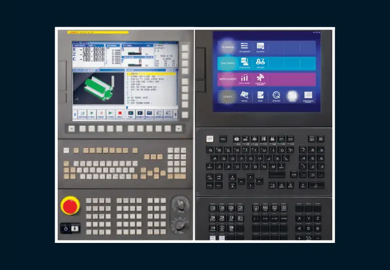
For example, the program window can be reached by pressing the MDA button on the control panel or by positioning the drum (Mode Select Switch). The program is written in edit mode.
Running The Program With Simulation Mode
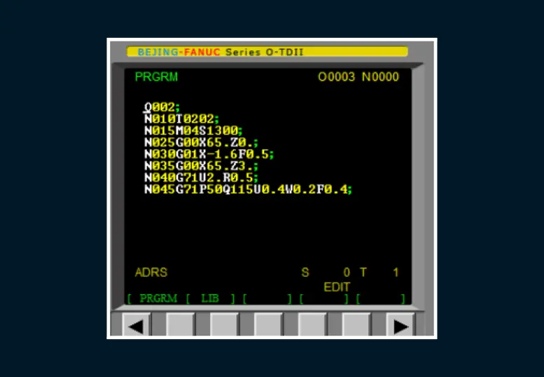
The CNC program can be written in the machine control unit as well as NC commands can be written via simulation programs on the computer. Both of these methods have a simulation feature. After the program is written and finished, these options are used to check whether the program is correct. Program blocks written with this option are checked one by one to find errors in the program. After the program is written, it must be tested.
When this option is entered, it asks you to enter the name of the program to be tested. When the program name is entered, the program is displayed line by line. The simulation of the operation can be examined, and it can be checked whether there is an error in the program.
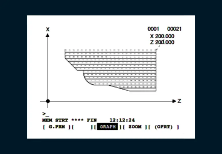
As each line written in the program from the rough material view of the workpiece is processed, it goes to its final state. The changes to the work piece seen during this time show how well the written program is.
During the simulation, errors caused by typographical errors are removed, and lines are corrected. As a result of repeated operations, an error-free, correct NC program target is reached.
Sequences Of Simulation On Fanuc Controlled Machines
- Call the program to be simulated.
- Press the AXIS INHIBT key (which locks the axes).
- Press the AUTO button.
- Press the AUX GRAPH button.
- Press the GRAP button from the bottom of the screen.
- Press the NORMAL button at the bottom of the screen.
- Press the CYCLE START button.
Sequences Of Simulation On Siemens Controlled Machines
- Press the Program Manager button.
- Hover over the program you want to run off the screen and open it.
- Press the AUTO button.
- Press the simulation button at the bottom of the screen to begin.
- Press the CYCLE START button.
NOTE:
After the simulation, do not forget to remove the cutting tools from the axis and send them back to the reference. The tools to be used in Siemens controlled machines must be reset before the simulation.

Testing The Machine In Slow Progress Mode (Dry Run)
The NC program created and simulated with the commands written on the computer or entered from the machine command panel will be tested in the real environment. For this, cutters and the workpiece to be processed are connected to the machine. The program is started when the machine is in its normal working position. The impact event of the machine’s cutters is typically in the G00 range. In order to prevent collisions, the Dry Run (trial operation mode) feature on the machine must be turned on.
When this feature is turned on, the G00 codes of the machine are turned off and the machine enters the slow progress mode. Thus, the collision situations of the cutter are determined beforehand, necessary corrections are made in the program, and the machine returns to normal mode. The machine operates at capacity in normal mode, but the setting is lowered for safety with the help of the button.
We can do this by turning the knob on the hand-adjustable part of the mirror rotation to the left. The operation of the general system dependent on this will also slow down. The process is continued in this way until the end. If there is no malfunction when the workpiece is fully formed, then the machine is still running below its full capacity in the next piece. After a few jobs, the machine should be running at full capacity.
NOTE:
In this operating mode, the progress button should not exceed 100%. If it is passed, the axes move more rapidly in Fanuc-controlled machines where the G1 command is active.
In SIEMENS-controlled benches, ROW must be active on the screen.
Running The Program
Operating In Line By Line Mode (Single Block)
In CNC machines, tool and part movements are predicted in the program for feed, cutting speeds, and chip removal. All machining operations are done automatically without operator intervention. Preparation operations can be performed by the operator or automatically carried out. If the programmer presses the SBL (Line by Line) button on the machine panel, the machine waits for an instruction from the operator to move to the next line at each command line in the sequence. It is necessary to press start to run the next line. If the operator presses the same button depending on the situation, the machine processes the next row. When the line operation is done, it stays there until the operator tells it what to do next.
NOTE:
We need to reduce the progress to zero before pressing start and turn on the progress after the line is checked.
Working In Auto Mode On Fanuc Controlled Machines
- Enter the tool length and the workpiece zero point.
- Call the program you want to run in EDIT mode.
- Press the Auto button.
- Press the SINGLE BLOCK button.
- Decrease progress for safety reasons.
- Press the CYCLE START button within the safety rules.
- See the position of X and Z (POS).
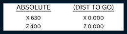
ABSOLUTE: Distances from the work-piece zero point.
DIST TO GO: Specify the distance the tool will travel on the workpiece.
Press the (CYCLE START) button in the safety rules.
Working In Auto Mode On Siemens Controlled Machines
- Enter the tool length and the workpiece zero point.
- Program manager Open the program you want to run.
- Press the Auto button.
- Press the SINGLE BLOCK button.
- Decrease progress for safety reasons.
- Select “CYCLE START” from the upper right corner of the screen.
NOTE:
Since the SINGLE BLOCK key is active, we have to press CYCLE START every time.
The DRY RUN mode should be active while approaching the part safely.
Checking The First Produced Work-piece
The first workpiece made in the step-by-step position is removed from the workbench and its dimensions are precisely controlled. The purpose of this process is to check whether the adjustments made give the correct result since the machine is controlled by a program.
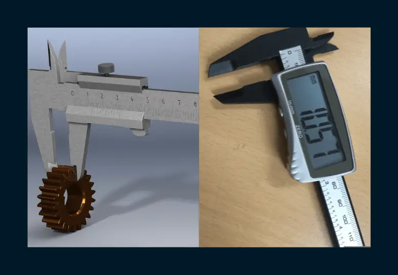
In the measurement process, other measurement and control tools such as digital calipers, micrometers, parameters, or gauges are used according to the sensitivity of the work and the tolerance value.
Correction Of Detected Measurement Differences
The necessary measurements of the first piece to be manufactured are made. It is to correct unwanted measurement differences as a result of measurement and control from the WEAR (Tool Wear) window. Here, the value found as a result of the measurement is the corresponding tool number in this window as the Z value level is entered. If an excess value is encountered as a result of the measurement, the value to be entered must be negative (-). Otherwise, it should be a positive (+) valence. The offset window where this operation will be performed is shown in the figure below.
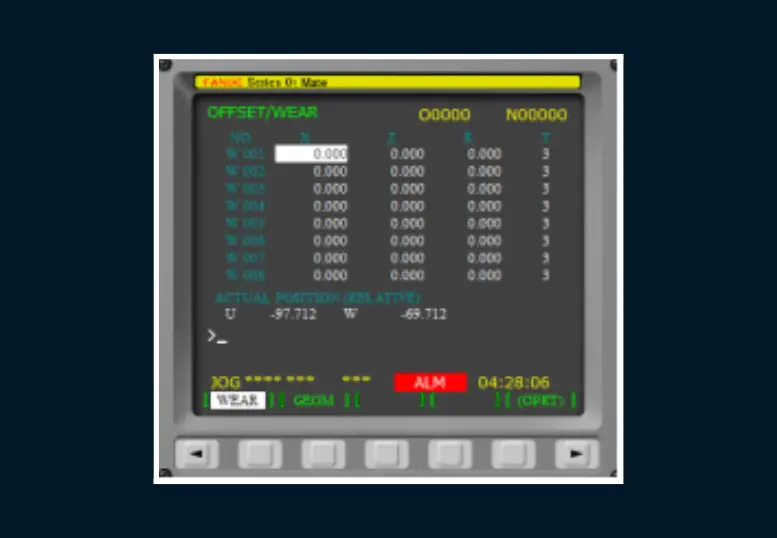
- Entering Dimensions
If there is an excess of 0.2 mm in diameter, the tool wear page is entered. It is called U-0.2 INPUT.
If there is an excess of 0.2 mm in length, it is called W-0.2 INPUT.
Operating In Serial Mode
If the first workpiece produced after all the preparatory work, SINGLE BLOCK and DRY RUN, is within the dimensions and tolerances we want, we can now operate the bench in series. The SINGLE BLOCK and DRY RUN functions are turned off. When you press the automatic button, the machine starts to do its job for each block written in the program. The actions taken are monitored after the protective cover.