CNC Lathe – Grooving with G Code Examples

What is Grooving?

The grooving operation allows us to machine circular channels on cylindrical part surfaces. These channels may be desired to be machined for various reasons. In this article, we will explain how to open channels with the grooving operation in a manual and CNC lathe. We will also learn how to adapt the operation to different groove types.

For example; The circlip grooves can generally be used to fix the bearings in a certain position on the cylindrical surface. At the same time, these channels are needed for part`s security reasons. Also, these grooves are used by engineers during design to ease the lubrication of rotating parts.

You can open these channels not only on cylindrical surfaces but also on the forehead of the cylindrical piece (face grooves).

What are the different types of grooving operation?

 There is three types of grooving operation to machine channels on cyrindirical, forehead surface of the part.

 1) OD(outer-diameter): It is used to open the grooves to the outer cylindrical surface.

 2) ID(Inner-diameter):It is used to open the grooves to the inner cylindrical surface.

 3) Face Grooving: It used for machining grooves to forehead surface of the part

CNC Lathe Grooving Program

In the CNC lathe, the groove can be opened using the G01 command with the groove pen. After determining the most suitable number of revolutions and advanced amount for grooving, the part where the grooving will be opened is approached with rapid (G00) progress. With the G01 command, the cutting tool plunges into the groove. Grooving to the periphery is achieved by moving in the X axis as in face turning.

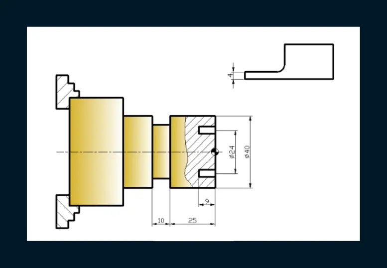
In the CNC lathe, a channel can be opened on the cylindrical surface as well as on the forehead of the part. An appropriate grooving cutting tool must be used for face grooving.
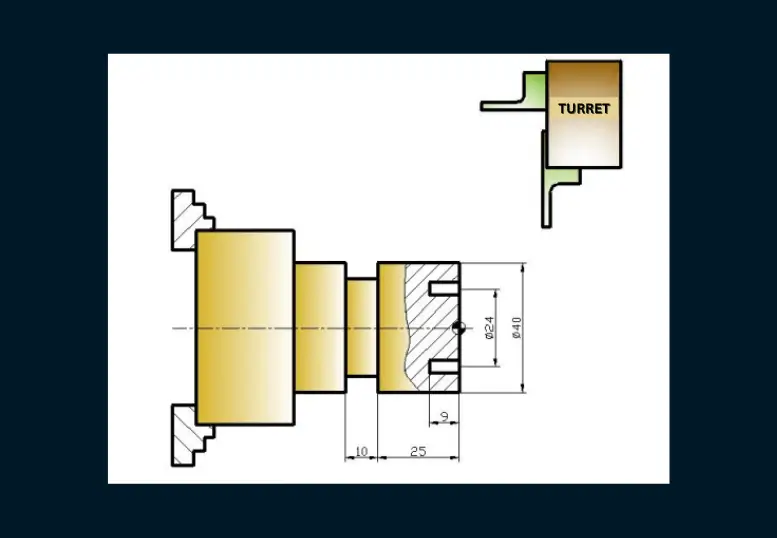
Channel opening process example.

Manual Programming

The set of commands used for manufacturing parts in CNC machine tools is called a part program. Part programs can be written in alphabetical, numeric, alphanumeric, etc. formats that the machine tool can understand. The feature of the part program is that it consists of commands that the CNC machine can understand and is written in a certain logical order from the beginning to the end.

Command Line:

N_ G01 X_ Z_ F_;
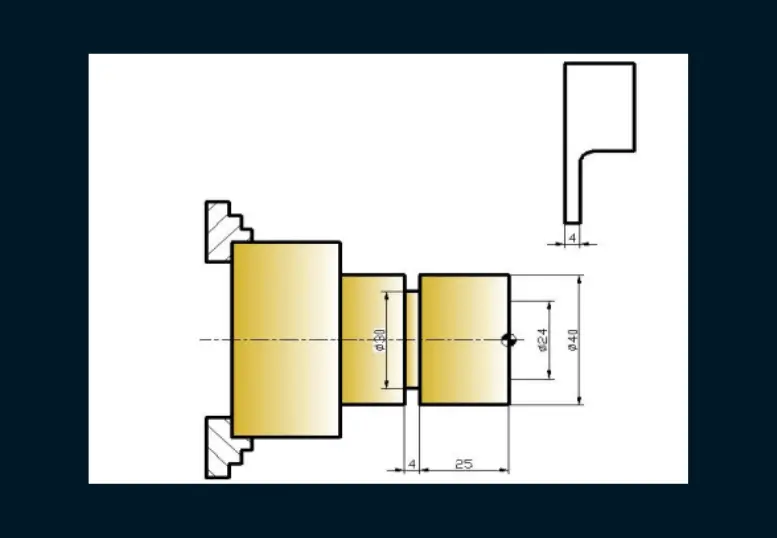
Example-1
  • Fanuc programming
O0023Program number
N5 G90 G54;Absolute measuring system and workpiece zero point selected
N10 T0101;Selecting the number 1 tool,
N15 G50 S1200 M04Turn the spindle counterclockwise at 1200 rpm. limitation
N20 G96 S180Feed under constant cutting speed. (Revolution by diameter)
N25 G0 X42 Z-29 M07Approaching X 42 mm, Z -29 mm at maximum speed and
turning on the coolant
N30 G01 X30 F0.15Chip removal up to X 30 mm with chip removal advance
N35 G0 X50 M09X 50 mm displacement at maximum speed and coolant closing
N40 Z150Z 150 mm offset at maximum speed
N45 M02End of program
  • Siemens programming
SIEMENS3Program number
N10 T01 D1 G90No. 1 tool selection, absolute programming
N20 S1200 M04Spindle 1200 rpm. counterclockwise turning
N30 G0 X42 Z-29 M08Docking X 42 mm, Z -29 mm at maximum speed and
turning on the coolant
N40 G1 X30 F0.15Chip removal up to X 30 mm with cutting feed
N50 G0 X50 M09X 50 mm offset at maximum speed and coolant shut off
N60 Z150Maximum speed Z 150 mm offset
N70 M02End of program
Example-2
FANUC PROGRAMMING
O0024Program number
N5 G90 G54Absolute measuring system and workpiece zero point selected
N10 T0303No. 3 tool selection
N15 G50 S1200 M04Turn the spindle counterclockwise at 1200 rpm. limitation
N20 G96 S180Feed under constant cutting speed. (Revolution by diameter)
N25 G0 X24 Z3 M08Docking X 24 mm, Z 3 mm at maximum speed and turning on the coolant
N30 G1 Z-9 F0.2Chip removal up to Z-9 mm with cutting feed
N35 G0 Z60 M09Max speed Z 60 mm offset and coolant shut off
N40 X80Maximum speed X 80 mm offset
N45 M02End of program
SIEMENS PROGRAMMING
SIEMENS7Program number
N10 T03 D3 G90No. 3 tool selection, absolute programming
N20 M04 S1200Spindle 1200 rpm. counterclockwise turning
N30 G0 X24 Z3 M08Docking X 24 mm, Z 3 mm at maximum speed and turning on the coolant
N40 G1 Z-9 F0.2Chip removal up to Z-9 mm with cutting feed
N50 G0 Z60 M09Max speed Z 60 mm offset and cooling shut off the fluid
N60 X80X 80 mm offset at maximum speed
N70 M02End of program

By Isaac Aloyan

Isaac Aloyan is a talented mechanical engineer with a background in machinery design and manufacturing. He completed his diploma from the Department of Machinery Design and Manufacturing at Kocaeli University and also graduated from Level 7 NZDE Mechanical Engineering at Manukau Institute of Technology (M.I.T). Isaac has developed strong expertise in various areas of mechanical engineering, including CNC programming and machining, vacuum mold design and production, manual machining, CAD and CAM, and thermoforming machine design and production. Also, he has educator experience in the area of CNC machinery and programming and mechanical design. With two decades of experience under his belt, Isaac has established a website called mechutopia.com to share his knowledge and help others who are interested in the field of mechanical engineering. The site is likely to feature a wealth of information, resources, and tips for those looking to learn about CNC machines, machining, mold production, and more. It is a testament to Isaac's dedication to the field and his commitment to helping others excel in sub-domains of mechanical engineering like design and manufacturing.