Introduction
CAD stands for Computer-Aided Design, and it is cutting-edge technology. With this digital software, you can easily design machines, spacecraft, buildings, etc. It gives a lot of power to you edit your drawings and even analyze with stress calculations like FEA systems. Moreover, these 3D models can be used to manufacture mechanical parts with computerized machines and CAM technology.
Some CAD packages with their usage areas;
| Software Name | Common Usage Areas |
|---|---|
| AutoCAD | Architecture, Engineering, Construction, 2D Drafting |
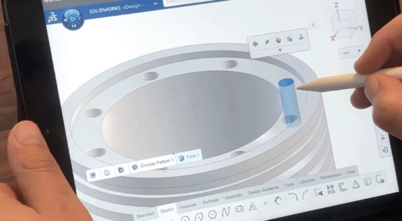
| SolidWorks | Mechanical Engineering, Product Design, 3D Modeling |
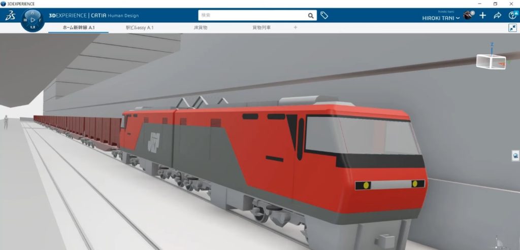
| CATIA | Aerospace, Automotive, Industrial Design, 3D Modeling |
| Revit | Building Information Modeling, Architecture, Construction |
| SketchUp | Architecture, Interior Design, 3D Modeling, Urban Planning |
| Inventor | Mechanical Design, Simulation, Visualization, Documentation |
| Creo (formerly Pro/ENGINEER) | Product Design, 3D Modeling, Simulation, Manufacturing |
| Fusion 360 | 3D Modeling, Manufacturing, Industrial Design |
| Rhino | Industrial Design, Architecture, 3D Modeling, Marine Design |
| TinkerCAD | 3D Modeling, Education, Prototyping |
| MicroStation | Architecture, Engineering, Construction, Geospatial |
| FreeCAD | Mechanical Engineering, Product Design, Architecture (Open Source) |
| Blender | 3D Modeling, Animation, Video Games, Visual Effects |
The History Of CAD
Dr. Patrick Hanratty was the one who came up with the idea for the first CAD system. In the late 1950s, Patrick Hanratty made the first tool for numerical programming called PRONTO. Later, he made the DAC (Design Automated by Computer) system. It was the first computer graphics program that let users interact with designs. It was also the first step toward making the CAD system.
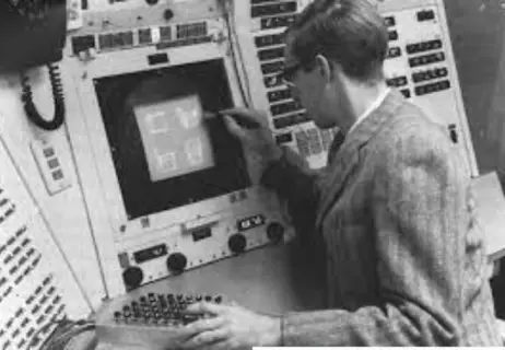
Ivan Sutherland came up with the SKETCHPAD system in 1963, which changed everything. The computer program was made at the Massachusetts Institute of Technology in the United States. It was the first time that a light pen could be used to draw on a computer screen. Sutherland’s system lets you change the drawn object, zoom in or out, and save the design so you could use it again later.
As part of his doctoral thesis, Sutherland told the critics what he had learned from his studies. People often think of Sutherland’s work as the first of many CAD systems and the beginning of the industry. Early work in this area grew quickly, and by the late 1960s, CAD was being used in the first large-scale commercial projects. With the rise of computers, technology kept getting better. In the 1980s, AutoCAD became the industry standard, and in the 1990s, Parasolid and ACIS were used for 3D design. All of these are still being used today.
Understanding the Mechanical Design Process
CAD systems bring a lot of good things for you. However, you still need to follow traditional mechanical design conventions. This is an important part of Product Life-Cycle Management (PLM). It consists of the best steps for designing a successful product. The primary mission of the CAD system is to make these steps easy to implement and manage. Product Life-Cycle Management consists of Concept design, Development, Production (Prototyping), Testing, and Refining the design.
- Creating concept and explaining the problem:
It’s the most important phase of designing parts. The product will be more realistic and satisfying the better the problem is defined. Also, you will determine the scope of the project in this phase.
- Prototyping:
After defining the problem, you should come up with ideas as soon as possible. Team brainstorming is very useful for this stage.
- Designing:
This step is where the product’s shape, size, and content are decided. In this step, tasks like making draft drawings and taking measurements are done. Cad Systems provides tools for creating 3D models and then drafts, manufacturing drawings, and blueprints easily.
- Calculation and Decision:
In this step, criteria like cost, functionality, market availability, quality, and the number of steps needed to make the product as quickly as possible are figured out and the best results are chosen. Also testing the mechanical design against the requirement must be done in this phase. Cad Systems provides FEA ( Finite Element Analysis) tools and animations to make design and test environments as close to reality as possible.
- Realization:
This is the step where the part or parts that are going to be made are planned out in detail. After this step is done, production begins which evolves a wide range of manufacturing methods like CNC machining, Injection Molding, etc.
Computer graphics and computer-aided design have changed the way people design in revolutionary ways. Because of this, universities have had to change their engineering programs, and Production Engineering has come to the forefront as a new field.
CAD Integration of Design and Manufacturing Staff in the Organization
Computer-aided design, or CAD, is the use of computer systems to help with the creation, development, analysis, and change of engineering designs. A CAD system is made up of three parts: hardware, software, and a user.
CAD hardware usually consists of a computer, one or more graphic display terminals, a keyboard, a printer, a plotter, and other peripheral hardware.
In general, a CAD system is made up of three main parts:
- Hardware is the computer and I/O units
- Operating System: Unix, Solaris, or Windows, OS
- Software: Topsolid, Pro-Engineer, CATIA, SolidWorks, etc.
CAD systems can be put into many different groups, such as Application Areas, which include mechanical, architectural, visual, and other areas. Modeling methods: 2D, 3D, Surface, etc.
Traditionally, engineering design is made by drawing out the design in detail on drawing tables and keeping a record of it.
A CAD system has these parts:
- Designer,
- Computers and other hardware used by designers (printer, plotter, etc.)
- General system software and CAD software are both types of software.
- Problem; design problem to be solved.
Key Benefits Of CAD
- Less work:
Because you don’t need to set up a classical drawing table and devices it is very fast to start and edit drawings.
- The error rate goes down:
Because CAD software uses some of the best tools, the number of mistakes made when designing by hand goes down by a lot. By making simulations that can be seen. Without portable production, it is made sure that the designs are understood.
- Easy editing:
CAD systems provide very sophisticated systems to fix errors in drawings. Like zoom, eraser, etc.
- Better and more efficient in less time:
For example, the OFFSET command in AutoCAD can be used to repeat parallel lines. With the ARRAY command, it’s easy to make shapes that repeat at regular intervals. With the HATCH command, you can make scan lines with just one click. When drawing a full assembly drawing of a machine, you don’t have to draw each bolt and nut individually. You can just take them from a standard library and put them in the right place, even you can make your own “Block” library. By making simulations that can be seen. Without portable production, it is made sure that the designs are understood.
- Reusing drafts:
Since the whole job is done with computer tools, there is no need to do the same thing twice. You can copy different parts of the draft, and design, and use them over and over again. Drawings and details can be made to any size and level of detail. So, there is less room for error when making things.
- Improved accuracy:
There is no doubt that manual drawings can never match the accuracy that CAD software can provide. You have the tools to measure a design’s skill, precision, and accuracy.
- Possibilities for drawing, putting together, and animating in 3D:
Design teams easily can design and collaborate for drawing large, complex assemblies. Animation can be used to show how the parts of a moving machine work together. With the manual method, you can’t make a 3D drawing. At most, you can draw pictures that look like they are in three dimensions. You can’t look at the piece you’ve drawn from top to bottom and see how it looks from different angles. CAD software lets you make changes to projects and drawings you’ve already made, and you can make as many copies as you want.
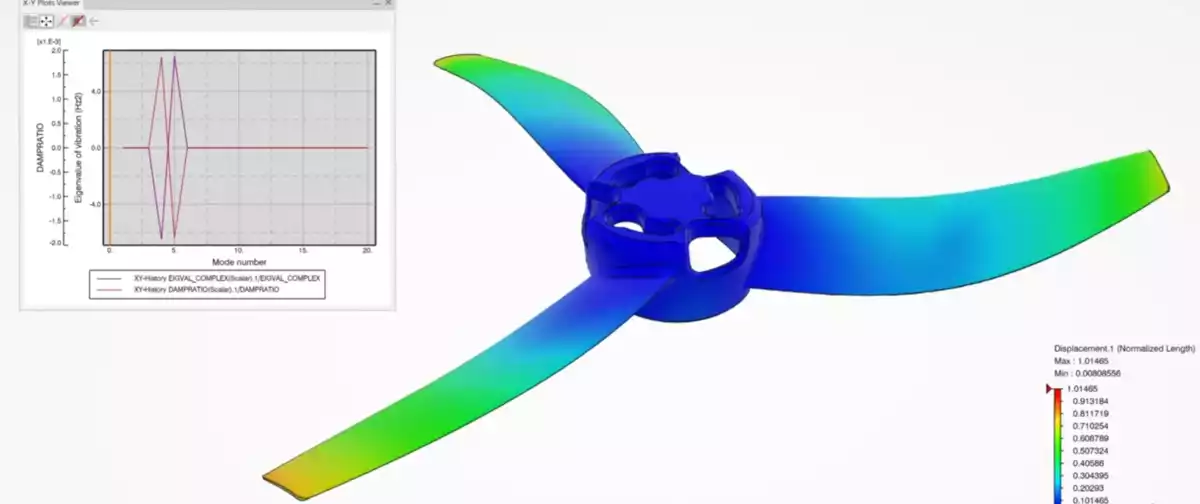
- Possibility of stress and strength analysis (FEA):
With computer-aided design programs, you can give the part you draw the properties of the materials it is made of (for example, Aluminum). By putting a load on any point, you can figure out where the part is weakest and if the load will cause the part to bend. Sharing is easy because CAD tools make it easy to save files in a format you can use again and again and send them without a lot of trouble.
You can send and share your work around the world easily, so other team workers can make changes. Today`s computer-aided design systems bring large teams together to achieve very big projects easily.
This is possible even with cloud technology. Better accuracy There is no question that manual drawings can never match the accuracy that CAD software can provide. You have the tools to measure a design’s skill, precision, and accuracy.
This table shows the advantages and disadvantages of computer-aided design (CAD)
| Advantages of Computer Aided Design (CAD) | Disadvantages of Computer Aided Design (CAD) |
|---|---|
| Less work | Expensive startup |
| Error rate goes down | Requires detailed training |
| Easy editing | Takes a long time to learn |
| Better and more efficient in less time | Managing software updates |
| Reusing code | Re-learning every new version of CAD system |
| Improved accuracy | Hard to find qualified designers |
| Possibilities for drawing, putting together and animating 3D |
In premises training |
Summary
In this article, we explained the advantages, design process, history, integration, and main benefits of the CAD system. You can see that CAD programs are much more advantageous than the old methods in every way. Today, using CAD is a necessity for a designer. Otherwise, it will fall behind the times and lose many job opportunities. My advice to you is to learn CAD systems as soon as possible.
Also, you can check this article about CAD/CAM systems.